Systems and methods for maintaining a drive signal to a resonant circuit at a resonant frequency

a technology of resonant frequency and drive signal, which is applied in the direction of electrial characteristics varying frequency control, computing operations for integration/differentiation, instruments, etc., can solve the problems of reducing the efficiency of power transfer, difficult to achieve tight magnetic coupling, and difficulty in achieving tight coupling

Active Publication Date: 2011-09-20
ETYMOTIC RES
View PDF105 Cites 29 Cited by
  • Summary
  • Abstract
  • Description
  • Claims
  • Application Information

AI Technical Summary

Benefits of technology

[0069]In certain embodiments, the system further includes an integrator configured to vary a control signal supplied to the oscillator based on the signal provided by the phase comparator, thereby adjusting the oscillator such that there is about a ninety degree phase shift between the oscillator output and the resonant circuit output, thereby maintaining the drive signal to the resonant circuit at about the resonant frequency.
[0070]In certain embodiments, the method further includes using an integrator to vary a control signal supplied to the oscillator based on the signal provided by the phase comparator, thereby adjusting the oscillator such that there is about a ninety degree phase shift between the oscillator output and the resonant circuit output, thereby maintaining the drive signal to the resonant circuit at about the resonant frequency.

Problems solved by technology

However, difficulty arises when attempting to provide a magnetic power source device that can couple with a variety of receiving devices without utilizing a close and predetermined physical relationship.
In other words, when the precise physical relationship between the primary and the secondary is not known, tight magnetic coupling may not be achieved.
For example, much of the magnetic flux produced by the primary winding may not be coupled to the secondary winding, thereby reducing the efficiency of power transfer and making the task of creating a sufficiently strong magnetic field in the vicinity of the secondary winding more difficult.
However, known approaches may be complex and / or may not provide desired results.
However, it has been discovered that known systems and methods do not address power losses associated with shunting of the magnetic path by the storage cell materials or reducing potential losses from the flux-concentrating magnetic material itself.
However, known systems and methods do not provide for battery charge need sensing that is simply implemented, does not require additional data paths, and does not significantly interfere with the charging operation.

Method used


Image

  • Systems and methods for maintaining a drive signal to a resonant circuit at a resonant frequency
  • Systems and methods for maintaining a drive signal to a resonant circuit at a resonant frequency
  • Systems and methods for maintaining a drive signal to a resonant circuit at a resonant frequency

Examples


Embodiment Construction

)

[0138]Embodiments of the present technology relate to systems and methods for inductively charging batteries. While certain embodiments are described in detail, the present inventions are not limited to such embodiments, rather, one skilled in the art will understand that the teachings herein are applicable to many types of battery powered devices that can benefit from the inductive charging systems and methods disclosed herein.

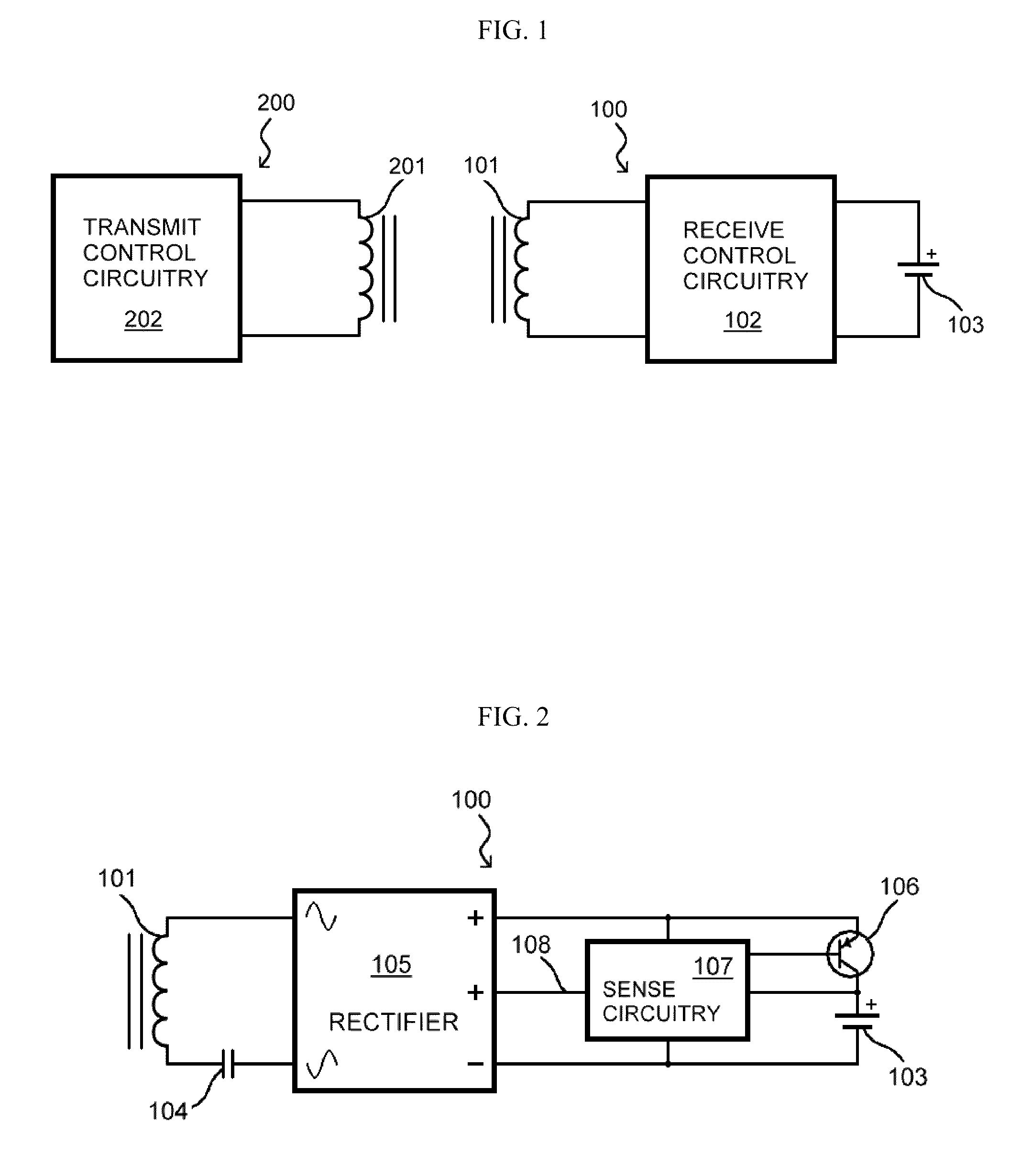
[0139]Referring to FIG. 1, a basic magnetically coupled battery charging system comprises transmit circuitry 200 and rechargeable battery assembly 100. Transmit circuitry 200 includes transmit (primary) coil 201 driven by transmit control circuitry 202, which produces an alternating current in coil 201. A portion of the magnetic field responsively generated by transmit coil 201 couples to receive (secondary) coil 101. The induced current in coil 101 passes through receive control circuitry 102 on the way to storage cell 103. Together, receive coil 101 and re...


PUM


Abstract

Systems and methods for maintaining a drive signal to a resonant circuit at a resonant frequency are provided. A system for maintaining a drive signal to a resonant circuit at a resonant frequency can include: an oscillator configured to provide an output to a phase comparator and a drive circuit, the drive circuit configured to provide a drive signal to a resonant circuit; a phase detector configured to receive a filtered version of the drive signal from the resonant circuit and provide a phase-indicating signal to the phase comparator; and the phase comparator, wherein the phase comparator is configured to provide a signal based on the phase difference between the oscillator output and the phase-indicating signal, wherein the signal from the phase comparator is used to control the frequency of the oscillator such that the phase difference converges to a fixed value.

Description

CROSS-REFERENCE TO RELATED APPLICATIONS / INCORPORATION BY REFERENCE[0001]U.S. Pat. No. 5,623,550 issued to Killion on Apr. 22, 1997 is incorporated herein by reference in its entirety.[0002]U.S. Pat. No. 7,206,426 issued to Julstrom et al. on Apr. 17, 2007 is incorporated herein by reference in its entirety.FEDERALLY SPONSORED RESEARCH OR DEVELOPMENT[0003][Not Applicable]MICROFICHE / COPYRIGHT REFERENCE[0004][Not Applicable]BACKGROUND OF THE INVENTION[0005]An electrical transformer transfers power from a primary winding to a secondary winding through the interaction of the windings' magnetic fields, with no conductive electrical contact. For many years, the notion of transferring power magnetically from a primary winding to a physically separable secondary winding has intrigued inventors. Reasons for coupling power magnetically include the safety and convenience of avoiding open electrical contacts and degradation that can afflict those contacts.[0006]Such technology has been utilized ...

Claims


Application Information

Patent Timeline
Patent Type & Authority Patents(United States)
IPC IPC(8): H03L7/085
CPCH02J7/025H03L7/02H02J7/00712H02J50/402H02J50/005H02J7/0044H02J50/12H02J50/70
Inventor JULSTROM, STEPHEN DRAKEMONROE, TIMOTHY SCOTT
Owner ETYMOTIC RES
Why Eureka
Try Eureka