Preparation of an article surface having a surface compressive texture

a technology of compressive texture and article, which is applied in the direction of manufacturing tools, machines/engines, forging/pressing/hammering apparatus, etc., can solve the problems of affecting the residual compressive stress state, affecting the ultimate performance of the article in its intended application, and degrading the aerodynamic performance of the airfoil, etc., to achieve the effect of low surface roughness

Active Publication Date: 2011-09-27
GENERAL ELECTRIC CO
View PDF26 Cites 16 Cited by
  • Summary
  • Abstract
  • Description
  • Claims
  • Application Information

AI Technical Summary

Benefits of technology

[0006]The present invention provides a method for preparing a surface of an article. The surface has a residual compressive stress that is desirable for delaying the onset of fatigue cracking. The surface also has a smooth surface finish with a surface texturing that has a quantitatively low surface roughness. Optionally, the surface texturing may have a directionally oriented surface texture pattern of the surface asperities (i.e., bumps or ridges). Such a directionally oriented surface texture pattern is advantageous in applications wherein there is a directionally oriented gas flow across the surface of the article, and the surface texture pattern is oriented relative to that directionally oriented gas flow. The gas flow may be, for example, air or combustion gas.
[0010]Thus, in the situation where the article surface is contacted by a directionally oriented gas flow when the article is in service to define a gas flow impingement direction on the article surface, the second processing step may be used to establish a directionally oriented surface texture pattern of surface asperities in the article surface, particularly where the article surface is nonplanar (i.e., curved in one or two dimensions). The directionally oriented surface texture pattern of surface asperities bears a selected relation to the gas flow impingement direction. In the case of an airfoil, this surface texture pattern is selected to optimize the performance of the airfoil.
[0013]The second processing step does not lessen the residual compressive stress state produced in the first processing step, but instead maintains and even increases the surface compressive stress state. Significantly, the second processing step does not utilize processing in which material is removed from the article surface. Such removal of material in the second processing step would tend to negate the residual compressive stress state produced in the first processing step by removing some of the thickness of material that is in the residual compressive stress state at the completion of the first processing step. Instead, the second processing step reduces the magnitude of the surface roughness that results from the first processing step, without removing any of the material that is in the residual compressive stress state. The second processing step actually increases the residual compressive stress state by working the surface without removing material. The second processing step must be performed after the first processing step, because the resulting final surface would be too rough if the second processing step were performed before the first processing step.

Problems solved by technology

However, such techniques for producing a residual compressive stress state at the surface may modify other properties of the surface, such as its smoothness, and consequently interfere with the ultimate performance of the article in its intended application.
An airfoil whose surface is mechanically worked to produce a residual compressive state at the surface, thereby improving the airfoil's fatigue performance, may have its surface finish disrupted to such a degree that the aerodynamic performance of the airfoil is degraded.
The known approaches for improving the surface finish in turn adversely affect the residual compressive stress state.
Consequently, achieving both a desirable residual compressive stress state and the necessary high-quality surface finish has not been possible using existing techniques.

Method used


Image

  • Preparation of an article surface having a surface compressive texture
  • Preparation of an article surface having a surface compressive texture
  • Preparation of an article surface having a surface compressive texture

Examples


Embodiment Construction

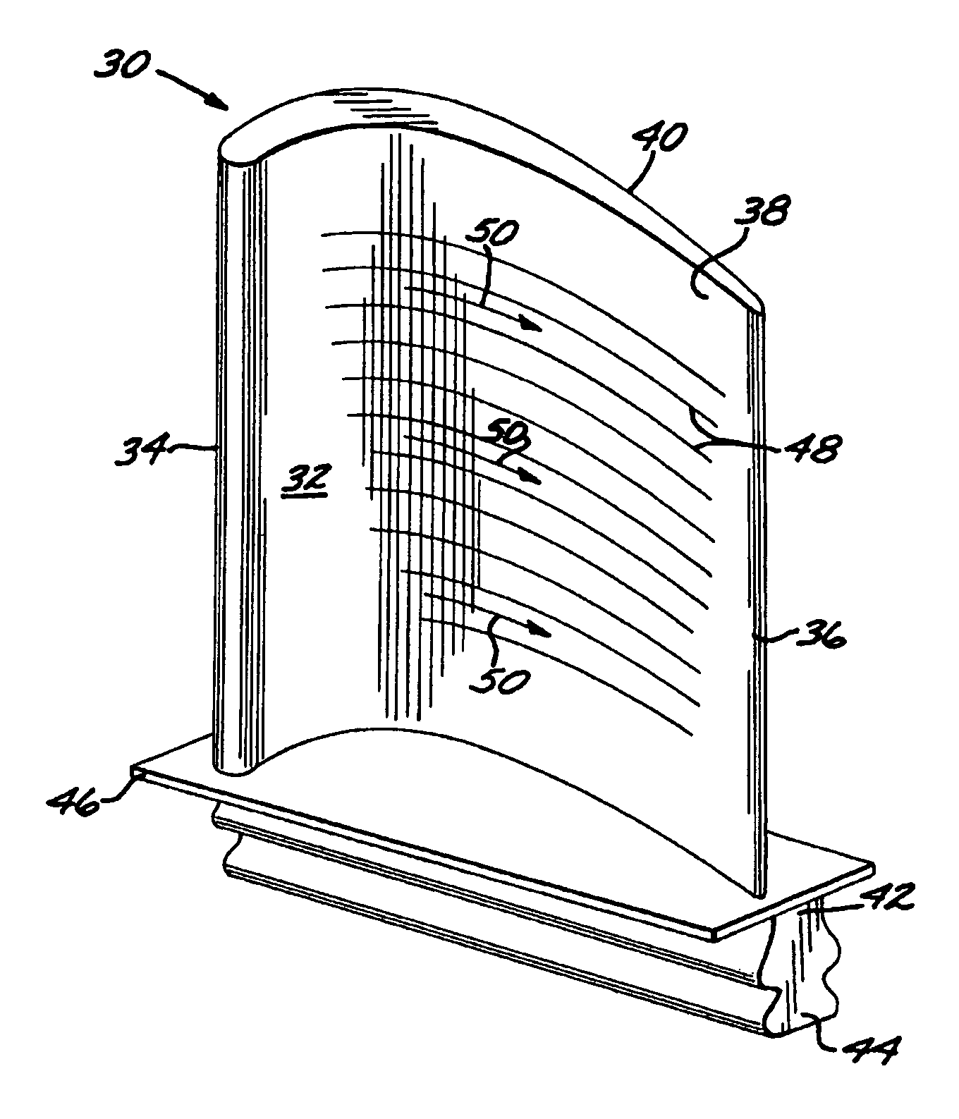
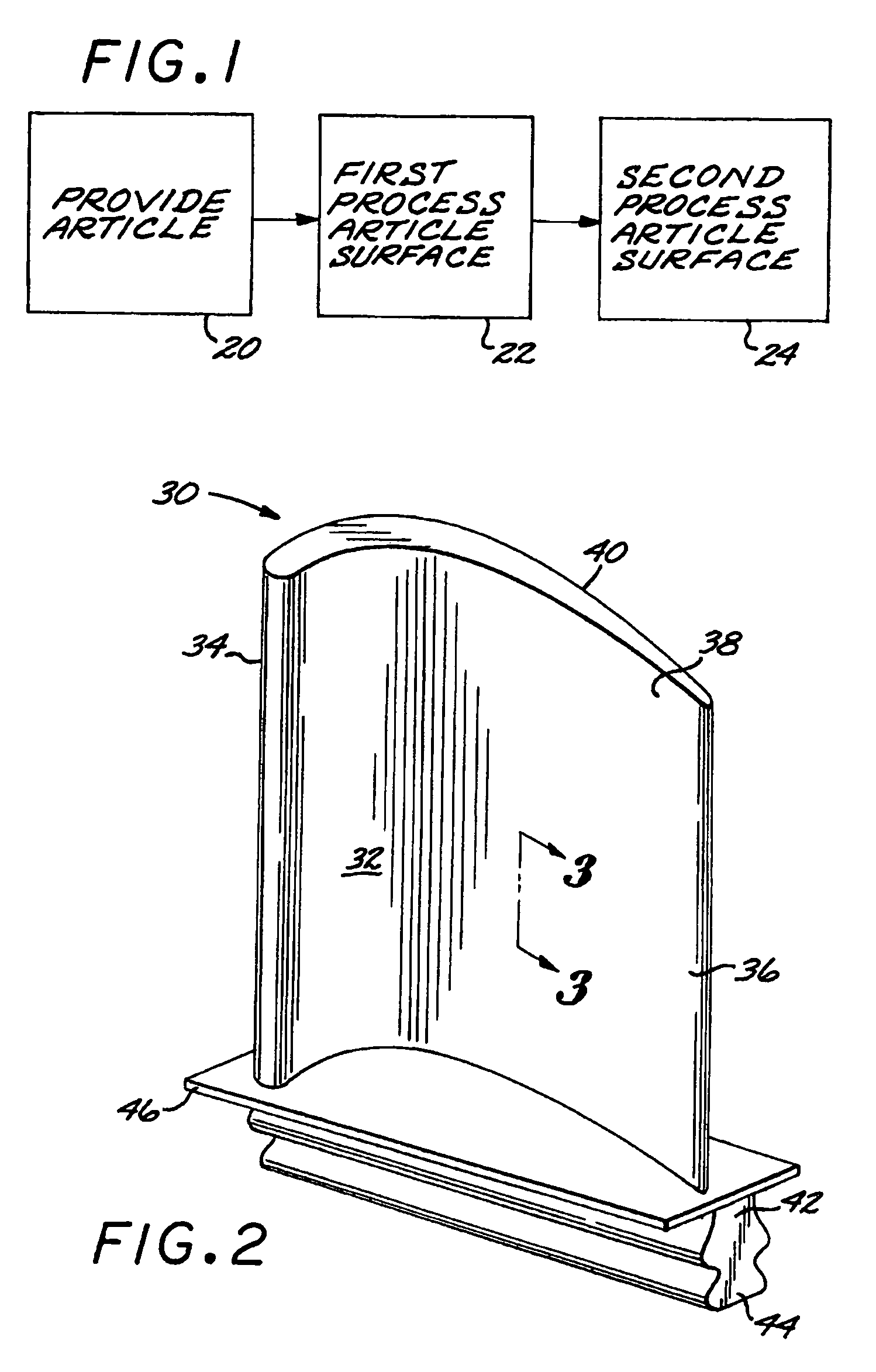
[0023]FIG. 1 illustrates a method for preparing a surface, and FIG. 2 depicts an article 30 of the most current interest. The article 30 having an article surface 32 is provided, step 20. In the illustrated embodiment, the article 30 is a gas turbine blade 34. (That is, the article 30 generically is a blade used in a gas turbine engine, but not necessarily in the turbine section. The article 30 may, for example be a compressor blade of the gas turbine engine.) The gas turbine blade 34 has an airfoil 36 including a pressure side 38, against which a flow of gas impinges during service operation, and an oppositely disposed suction side 40. The gas turbine blade 34 further includes a downwardly extending shank 42, and an integral attachment in the form of a dovetail 44, which attaches the gas turbine blade 34 to a gas turbine disk (not shown) of the gas turbine engine. A platform 46 extends transversely outwardly at a location between the airfoil 36 and the shank 42 and dovetail 44.

[002...


PUM

PropertyMeasurementUnit
residual compressive stressaaaaaaaaaa
surface roughnessaaaaaaaaaa
surface textureaaaaaaaaaa

Abstract

A method for preparing a surface includes providing an article having an article surface, thereafter first processing the article surface to establish a first residual compressive stress state and a first surface roughness in the article surface, and thereafter second processing the article surface by surface compressive texturing to establish a second residual compressive stress state and a second surface roughness in the article surface. The second surface roughness is quantitatively less than the first surface roughness, and substantially no material is removed from the article surface in the step of second processing.

Description

[0001]This invention relates to the preparation of the surface of an article, and more particularly to producing a beneficial surface texture and residual stress state in the article surface.BACKGROUND OF THE INVENTION[0002]The surface state of an article often has an important effect on the performance of the article. For example, corrosion and oxidation damage resulting from exposure to an adverse environment are largely controlled by the character of the surface of the article. A protective layer may in some circumstances be applied to the surface of the article to improve its corrosion and oxidation resistance.[0003]In another example, the fatigue resistance of an article, which is subjected to fatigue loading in service, is improved if the surface of the article is in a residual compressive stress state. The residual compressive stress state suppresses the initiation and propagation of fatigue cracks that would otherwise start at the surface and propagate into the interior of t...

Claims


Application Information

Patent Timeline
Patent Type & Authority Patents(United States)
IPC IPC(8): B21C37/30B24B39/00
CPCB23P9/00B23P9/02B24C1/10C21D7/06C21D7/08F01D5/00C21D10/00Y10T29/4932F05D2250/60Y10T29/476Y10T29/479
Inventor LUNA, ALBERTOWESSELS, JEFFREY F.LOMBARDO, DALE R.
Owner GENERAL ELECTRIC CO
Why Eureka
Try Eureka