Strip assembly

a strip assembly and strip technology, applied in the field of strip assembly, can solve the problems of very limited power consumption, achieve the effect of preventing the infiltration of dirt, ensuring the operation of the strip assembly, and preventing the strip from sticking

Active Publication Date: 2011-09-27
SUNWAVES BV
View PDF12 Cites 11 Cited by
  • Summary
  • Abstract
  • Description
  • Claims
  • Application Information

AI Technical Summary

Benefits of technology

[0017]In all cases, it is advantageous to integrate the assembly between two externally attached plates or the like. These may be two parallel plates between which the strip assembly is positioned but it is also possible to use what is known as a cushion foil and to attach the strip assembly according to the invention in the cushion. Obviously, other constructions are also possible. Attachment between two protective layers largely prevents the infiltration of dirt and moisture and ensures operation of the strip assembly even over a relatively longer period of time.
[0018]The further electrodes can contain any construction conceivable in the art. According to a particular embodiment, the further electrodes are configured as wires (grid). This has the advantage of not impeding or scarcely impeding the passage of light. In addition, this has the advantage that the thickness of these wires allows them to act as spacers with respect to a surface, thus preventing the strips from sticking.

Problems solved by technology

Power consumption is very limited, so the intended displacement can be carried out using very little energy.

Method used


Image

  • Strip assembly
  • Strip assembly
  • Strip assembly

Examples


Embodiment Construction

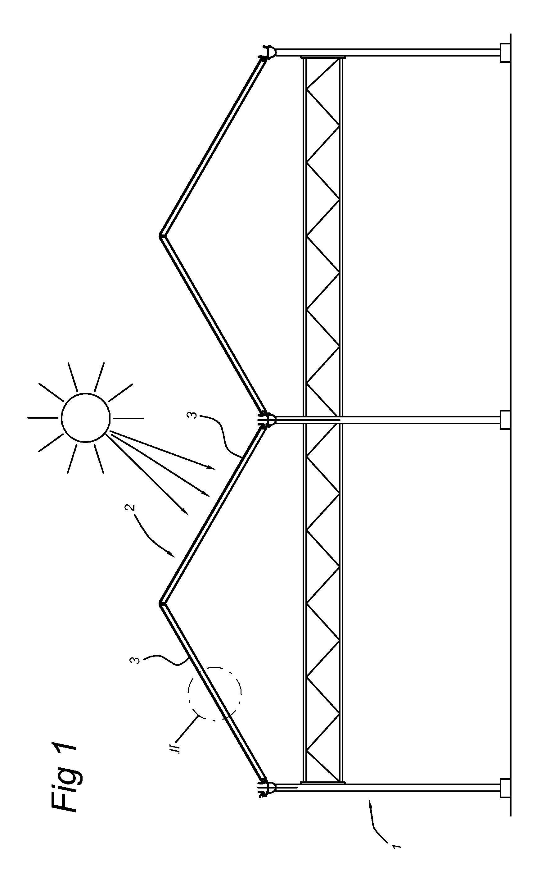
[0026]In FIG. 1, reference numeral 1 denotes a greenhouse. The greenhouse consists of a number of roof sections 2 and each roof sections is constructed from panels 3. The panels 3 are preferably oriented such that the angle which the panels form with respect to incident solar radiation at the moment at which the protection has to be most effective is approximately 90 degrees.

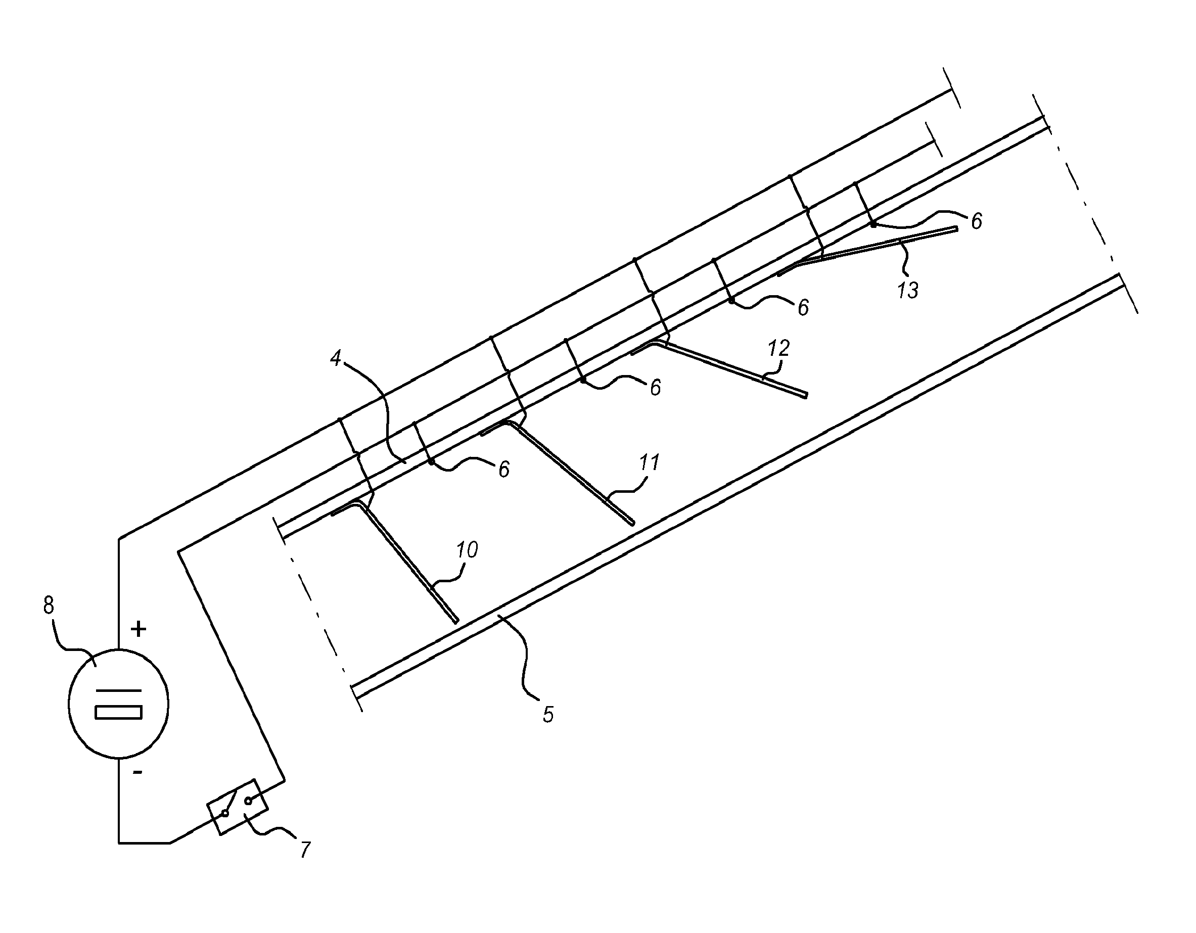
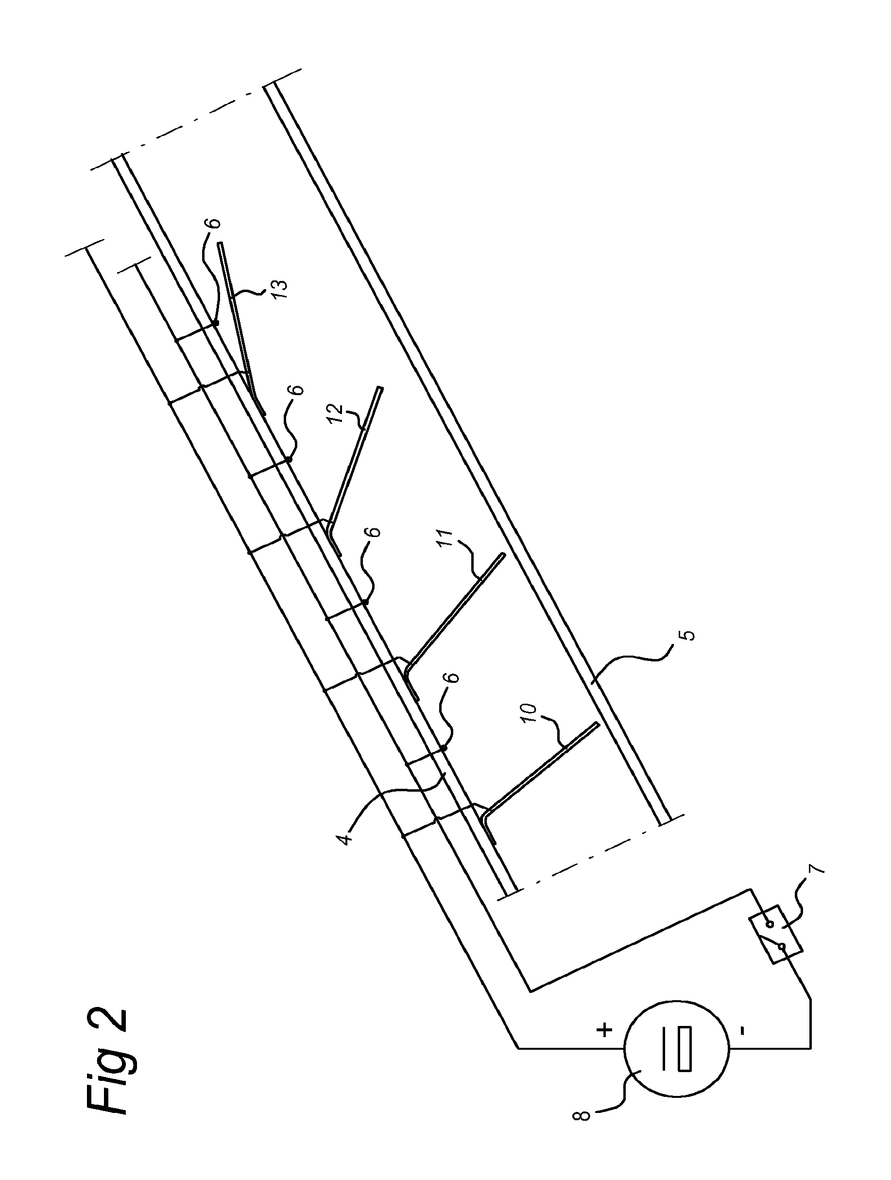
[0027]FIG. 2 shows a detail of the panel 3. The panel consists of two remote translucent plates 4 and 5. The plates may be glass plates but also plastics materials plates and the like. The strip or slat assembly according to the invention is attached between these plates. The strip assembly consists of a number of translucent further electrodes 6 and strips or electrodes 10-13. In FIG. 2, the strips 10-13 are shown in all cases in a different position for the sake of clarity. The further electrodes 6 are configured as grid and connected to the first pole of a schematically illustrated voltage source, whereas the...


PUM


Abstract

Strip assembly consisting of a number of strips hingeably attached to influence or not to influence light. Strips can be displaced between two positions by static charging/discharging with respect to a support attached near the strip. A voltage source provides the strips/further electrodes with the respective voltage. The strips can be configured to be (partially) non-transparent, allowing light effects to be obtained. In addition, it is possible to configure various strips differently. The strips preferably consist of a foil material allowing an especially simple construction with the aid of a film hinge. Suitable materials include polycarbonate, polyester or plastics material based on aromatics. The surface resistance is preferably at most 1000 MΩ. A broad range of uses are possible. One use is that in greenhouses but the present invention can also be applied at other locations where protection from light is necessary or specific light effects are desired.

Description

STATEMENT REGARDING FEDERALLY SPONSORED RESEARCH OR DEVELOPMENT[0001]NoneTHE NAMES OF THE PARTIES TO A JOINT RESEARCH AGREEMENT[0002]NoneINCORPORATION-BY-REFERENCE OF MATERIAL SUBMITTED ON A COMPACT DISC[0003]NoneBACKGROUND OF THE INVENTION[0004](1) Field of the Invention[0005]The present invention relates to a strip assembly comprising a carrier provided with a number of tiltable strips.[0006](2) Description of Related Art Including Information Disclose[0007]A strip assembly of this type is generally known in the art. In greenhouses, in particular, ever more stringent requirements are being placed on screening. This concerns the prevention of both undesirable irradiation of sunlight and undesirable emission of growth light. Strips or slats are one possibility for regulating the desired amount of passing light. Known in the art are mechanical constructions which, owing to their complexity, have never been used on a large scale. A further known construction consists of the use of mag...

Claims


Application Information

Patent Timeline
Patent Type & Authority Patents(United States)
IPC IPC(8): A01G9/00
CPCE06B9/264A01G9/222Y02A40/25
Inventor MARIA RUITER, JACOBUS CHRISTIAAN GERARDUS
Owner SUNWAVES BV
Why Eureka
Try Eureka