Low pressure vacuum resin infusion system

Active Publication Date: 2011-10-04
QUENNEVILLE MARC A +1
View PDF6 Cites 8 Cited by
  • Summary
  • Abstract
  • Description
  • Claims
  • Application Information

AI Technical Summary

Benefits of technology

[0016]In all four embodiments, the molding process can take place in a vacuum or in the absence of a vacuum. The presence of a vacuum enhances the process but the invention includes structure and method steps that are novel even in the absence of a vacuum.
[0017]In the first embodiment, a mold for making a preselected monolithic part is mounted atop the rotatably mounted support table for rotation within the vacuum chamber. The mold includes at least one small opening formed therein so that the interior of

Problems solved by technology

The manufacturing of large molded objects, such as boat hulls, large blades for an electricity-generating wind turbine, and the like, is problematic.
Such large objects are typically molded by a time-consuming manual process.
This drives up the cost of the individual products.
Items made by manual labor are also more likely to be of inconsistent quality as no two products will be exactly

Method used


Image

  • Low pressure vacuum resin infusion system
  • Low pressure vacuum resin infusion system
  • Low pressure vacuum resin infusion system

Examples


first embodiment

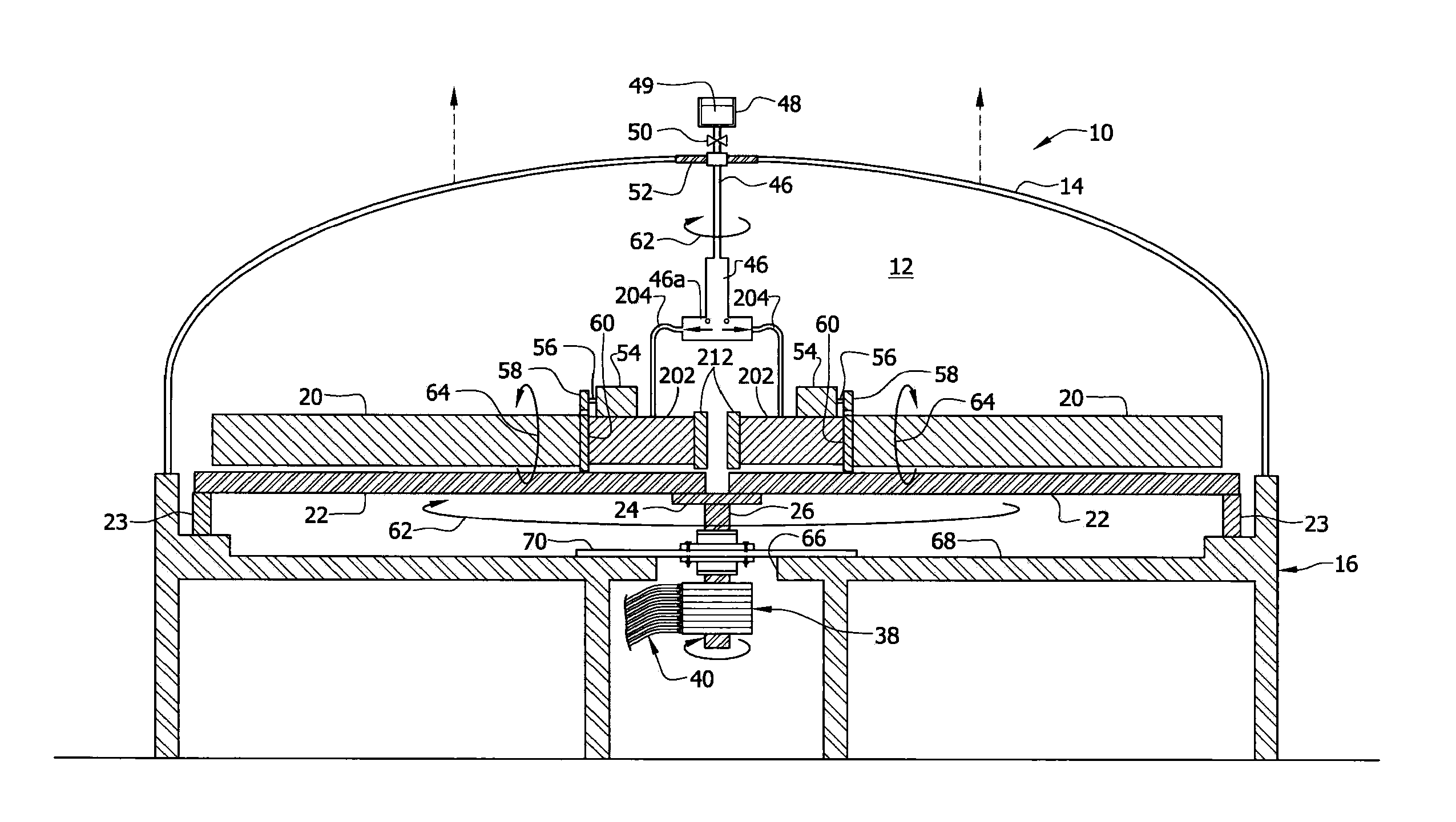
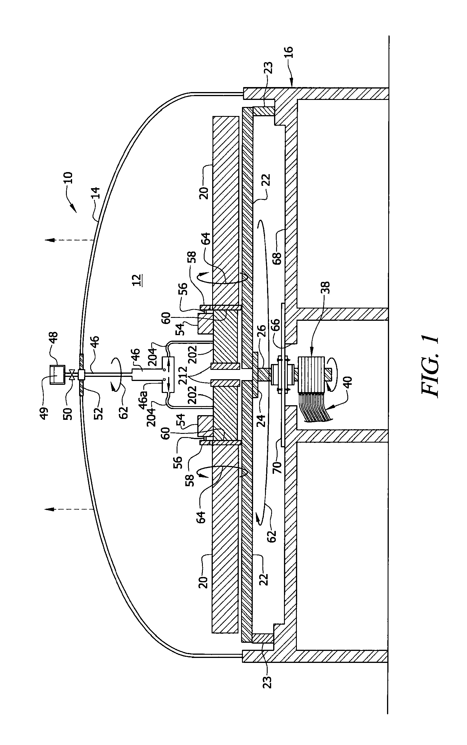
[0071]Although it is advantageous to position each part mold 20 within a vacuum, it is not necessary to enclose the entire apparatus in a monolithic vacuum chamber or atmospheric cofferdam 12 as in the

second embodiment

[0072]In FIG. 3A, large vacuum chamber 12 is eliminated. Instead, each part mold 20 having micro perforations 137 formed therein is individually enclosed within a vacuum housing or atmospheric cofferdam 110 dedicated to it. Far less energy is needed to create a vacuum in such smaller housings 110 vis a vis the larger vacuum chamber 12. Moreover, the smaller housings 110 are safer to use than the larger housing 12 because a worker might be in the larger housing when another unaware worker closes the vacuum chamber and begins operating the apparatus. Only two housings 110 are depicted in FIG. 3A to simplify the drawing but it should be understood that more of such housings may be symmetrically arranged on the supporting surface.

[0073]FIG. 3B depicts a third embodiment like that of the second embodiment but where support table 22 is oriented in a vertical plane for rotation about a horizontal axis.

fourth embodiment

[0074]A fourth embodiment including a vacuum chamber or atmospheric cofferdam 120 for making hollow spherical objects is depicted in FIGS. 4-13. This structure is easily adaptable to making hollow non-spherical seamless objects such as aircraft fuselages, natural gas tanks, bus bodies, high pressure tanks, car bodies, wind generator blades, and the like as well.

[0075]Atmospheric cofferdam 120 includes a box-like main body 122 having lid or closure means 124. In this particular embodiment, an elongate convexity 126 is formed in lid 124 to accommodate a spherical object. The convexity reduces the amount of air that must be pumped from atmospheric cofferdam 120 relative to the amount of air that would need to be removed if main body 122 were deep enough to accommodate a spherical object without said convexity formed in lid 124.

[0076]Vacuum pump 128 is in fluid communication with the interior of vacuum chamber 120 through conduit 129. Motor 130 has power take off shaft 131 that extends ...


PUM

PropertyMeasurementUnit
Lengthaaaaaaaaaa
Pressureaaaaaaaaaa
Centrifugal forceaaaaaaaaaa

Abstract

A mold assembly includes a support table mounted for rotation within a vacuum chamber. A plurality of hollow part molds is radially disposed about an axis of rotation of the support table. Each part mold has fiber architecture disposed between an inflatable bladder and internal walls of the part mold. A first motor rotates the support table and resin is urged by centrifugal force to flow along the length of each part mold until the fiber architecture is thoroughly impregnated with resin. A second motor spins each part mold about an axis of rotation of the part mold to ensure that the resin migrates radially outwardly relative to the interior wall surface of each part mold. The resulting product is a monolithic, seamless part having no voids.

Description

CROSS-REFERENCE TO RELATED APPLICATIONS[0001]This disclosure is a continuation-in-part and claims priority of U.S. patent application Ser. No. 11 / 967,340 filed by the same inventor on Dec. 31, 2007, now U.S. Pat. No. 7,722,348, entitled “Vacuum Assisted Molding.” That disclosure is incorporated in its entirety into this application by reference.BACKGROUND OF THE INVENTION[0002]1. Field of the Invention[0003]This invention relates to vacuum assisted molding. More particularly, it relates to fabrication of hollow, seamless composite elements of any size using a low pressure vacuum infusion system supplemented by multiple cooperative centrifugal forces.[0004]2. Description of the Prior Art[0005]The manufacturing of large molded objects, such as boat hulls, large blades for an electricity-generating wind turbine, and the like, is problematic. Such large objects are typically molded by a time-consuming manual process. This drives up the cost of the individual products. Items made by manu...

Claims


Application Information

Patent Timeline
IPC IPC(8): B29C70/48
CPCB29C70/323B29C70/326B29C70/446B29C70/48B29L2031/7734Y10S425/014
Inventor QUENNEVILLE, MARC A.QUENNEVILLE, STEPHEN M.
Owner QUENNEVILLE MARC A
Why Eureka
Try Eureka