System and method for printing a continuous web employing a plurality of interleaved ink-jet pens fed by a bulk ink source

a technology of interleaved ink-jet pens and continuous web, which is applied in the direction of printing, typewriters, spacing mechanisms, etc., can solve the problems of prone to speed and reliability limitations, inability to provide color printing, and inability to print color, etc., to achieve convenient duplex printing, maintain the flatness of the web, and ensure the effect of quality

Inactive Publication Date: 2011-10-11
ROLL SYST
View PDF16 Cites 23 Cited by
  • Summary
  • Abstract
  • Description
  • Claims
  • Application Information

AI Technical Summary

Benefits of technology

[0010]This invention overcomes disadvantages of the prior art by providing a system and method for printing continuous web that employs an array of interleaved ink-jet pens that are arranged to receive bulk ink through a manifold. The manifold and pens are mounted on a framework in groups of imagers suspended over the web feed path. The manifold includes a plurality of self-sealing quick-disconnect couplings that each serve a discrete ink-jet pen. The pens are also interconnected with a data connector that provides clock signals from a controller also interconnected with the web feed drive. In this manner, the pens lay down ink in a registered manner across the full width of the web. In an illustrative embodiment, the pens are organized into two parallel, multi-pen arrays that are each diagonally oriented with respect to the feed direction. The feed path allows for duplex printing with a second web-side's array located on a lower level of the device, generally beneath the first-side's array. Each level of the device maintains the flatness of the web using a vacuum surface comprising a plurality of holes in communication with a vacuum source. Duplex printing is facilitated due to the inherent length of the feed path. The printed part of the web is free of contact over predetermined lengths that ensure sufficient time for the drying of ink, typically achieved through a combination of absorption into the paper and some evaporation into the atmosphere.
[0011]A set of optional, movable, spot-printing ink-jet arrays can be located in an imager units that ride on carriages, which are movable in a widthwise direction. These movable arrays include an ink-feed mechanism for bulk ink and appropriate quick-disconnect couplings for ease of cartridge / pen replacement. In an illustrative embodiment, the movable arrays can be interconnected to a system for determining / reporting the widthwise location of the array. Each fixed array or group of movable arrays is interconnected with a discrete quick-change manifold that defines a channel in communication with a plurality of dripless quick-disconnect couplers. The couplers allow the feed tubes of individual cartridges / pens to be attached and detached for servicing, color change, etc. Each manifold is fed by a pressurized supply of bulk ink provided by a sealed ink bag via a pump and a pressure regulator. The pressure regulator includes a bleed valve. The manifold is also connected to a vacuum sensor assembly having a check valve that communicates with a vacuum sustaining draw pump. The draw pump withdraws excess ink and maintains the needed negative pressure to prevent ink from seeping out of pen nozzles.
[0012]Each manifold receives ink via a regulator tank that maintains a predetermined ink level using a float switch. The level falls as ink is drawn and the switch activates the bulk-ink-supply feed pump to restore the level. A headspace containing air resides above the ink, with a small pinhole to allow for air replacement as the level rises and falls, but most air is unchanged and saturated with ink vapor to prevent ink-dryout. Each manifold also includes a standpipe that exhausts any air bubbles present in the manifold's supply of ink through a check valve arrangement. The standpipe is in communication with a connection from the vacuum sustain pump. The vacuum sustain pump also connects to a downstream waste tank with an overflow sensor. Any ink flushed through the vacuum sustain line is exhausted in the waste tank. A variety of other level sensors at various locations in the ink-feed fluid circuit are used to monitor levels and detect failures to feed / clogs. The ink controller uses this information to control the pumps and / or issue alarm / stop signals to the printer controller and operator. Also, the use of quick-disconnect fittings, removable manifolds / pens, and peristaltic pumps with removable wetted elements, makes changing ink colors on the fly possible and relatively easy to accomplish.

Problems solved by technology

However, this approach uses expensive color toner and may be prone to speed and reliability limitations.
Hence, a conventional ink-jet printer with traversing head(s) is seldom suitable for providing color print to a high-speed moving web.
In addition, the internal ink supply of even the largest, commercial ink-jet cartridge is relatively small, requiring cartridges to be frequently replaced and / or manually refilled.
The replenishment of ink / cartridges would, thus, prove inconvenient and time-consuming for a large production run—particularly where only a small number of cartridges on a traversing carriage are used.

Method used


Image

  • System and method for printing a continuous web employing a plurality of interleaved ink-jet pens fed by a bulk ink source
  • System and method for printing a continuous web employing a plurality of interleaved ink-jet pens fed by a bulk ink source
  • System and method for printing a continuous web employing a plurality of interleaved ink-jet pens fed by a bulk ink source

Examples


Embodiment Construction

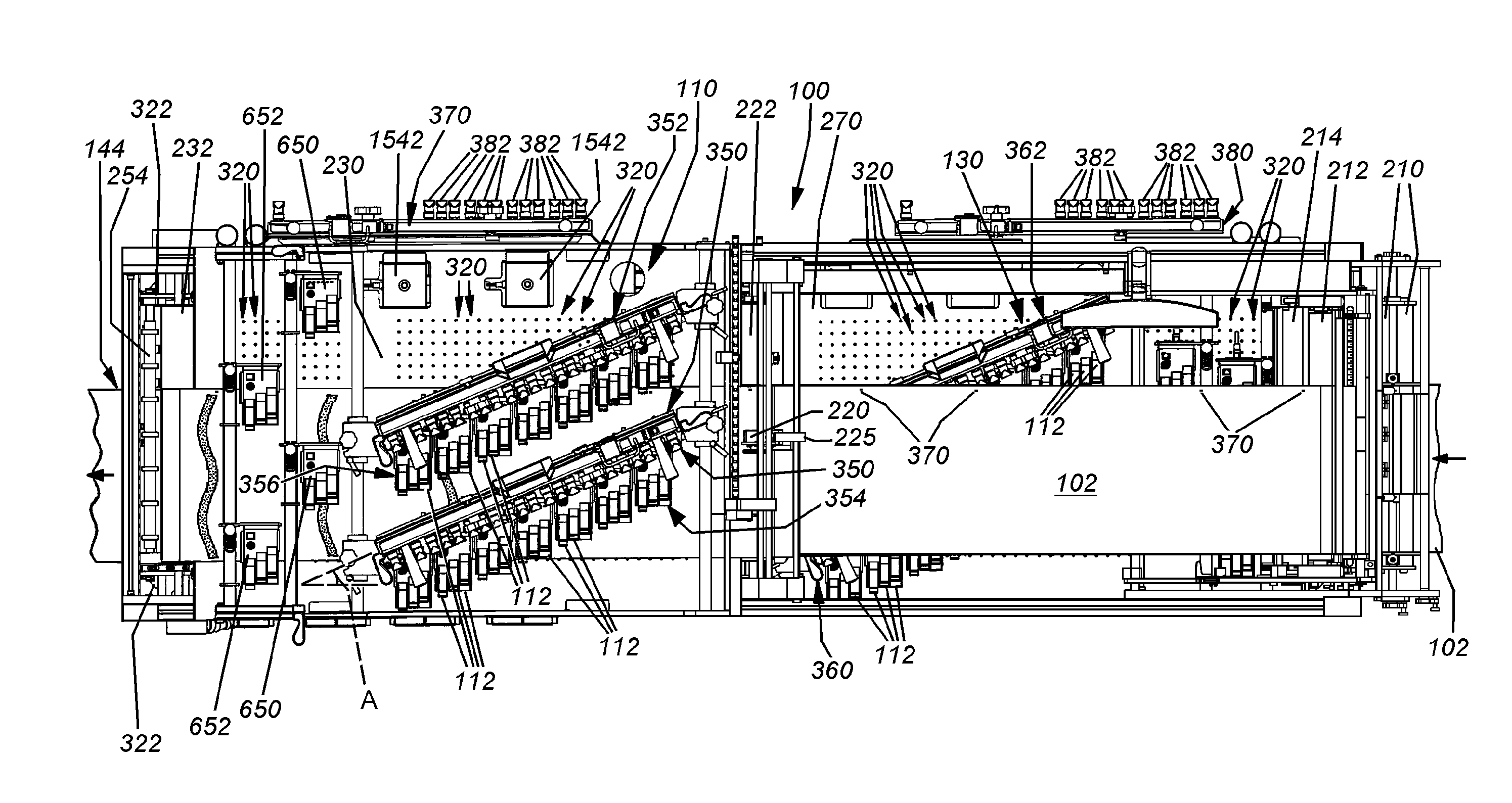
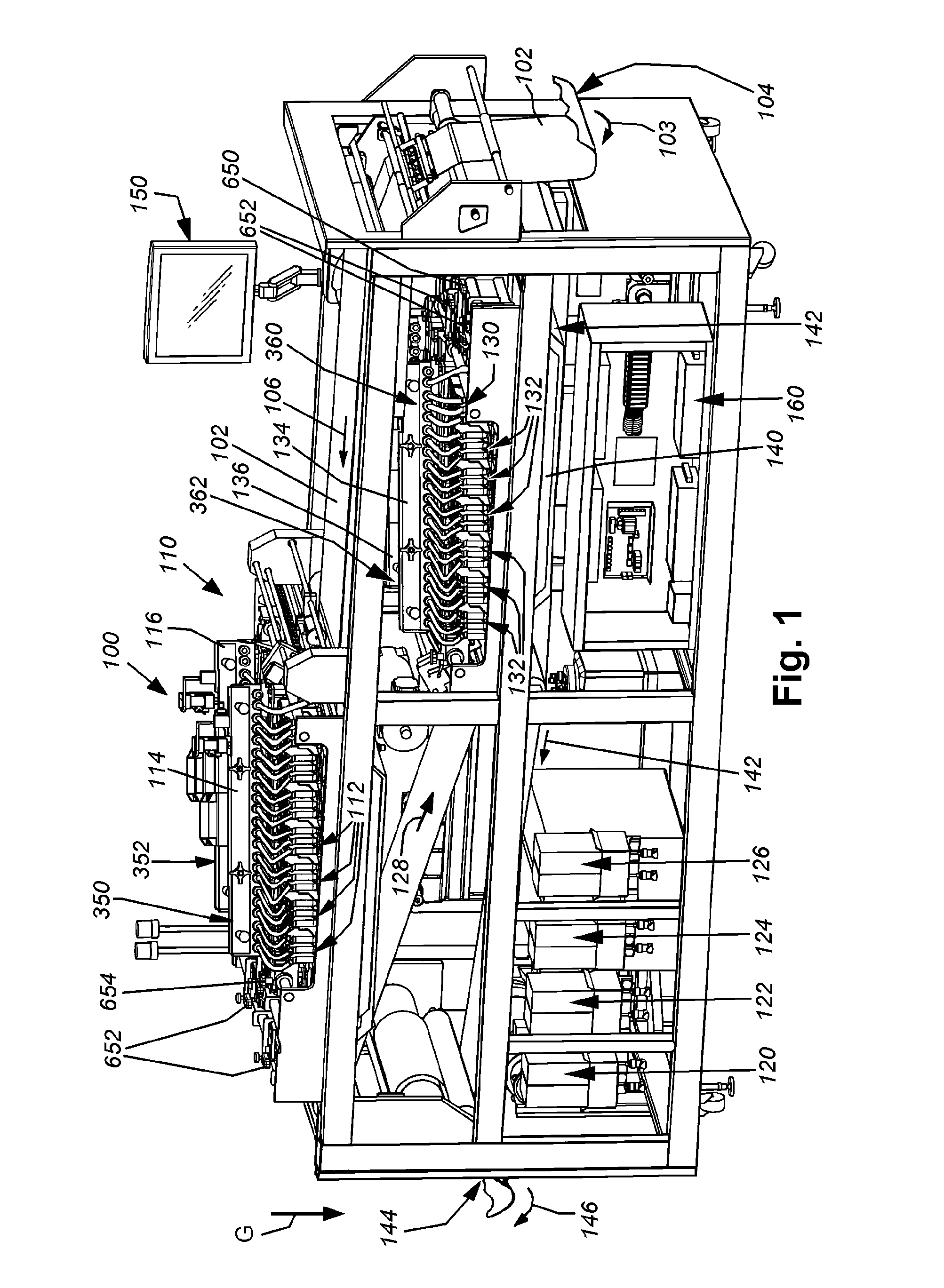
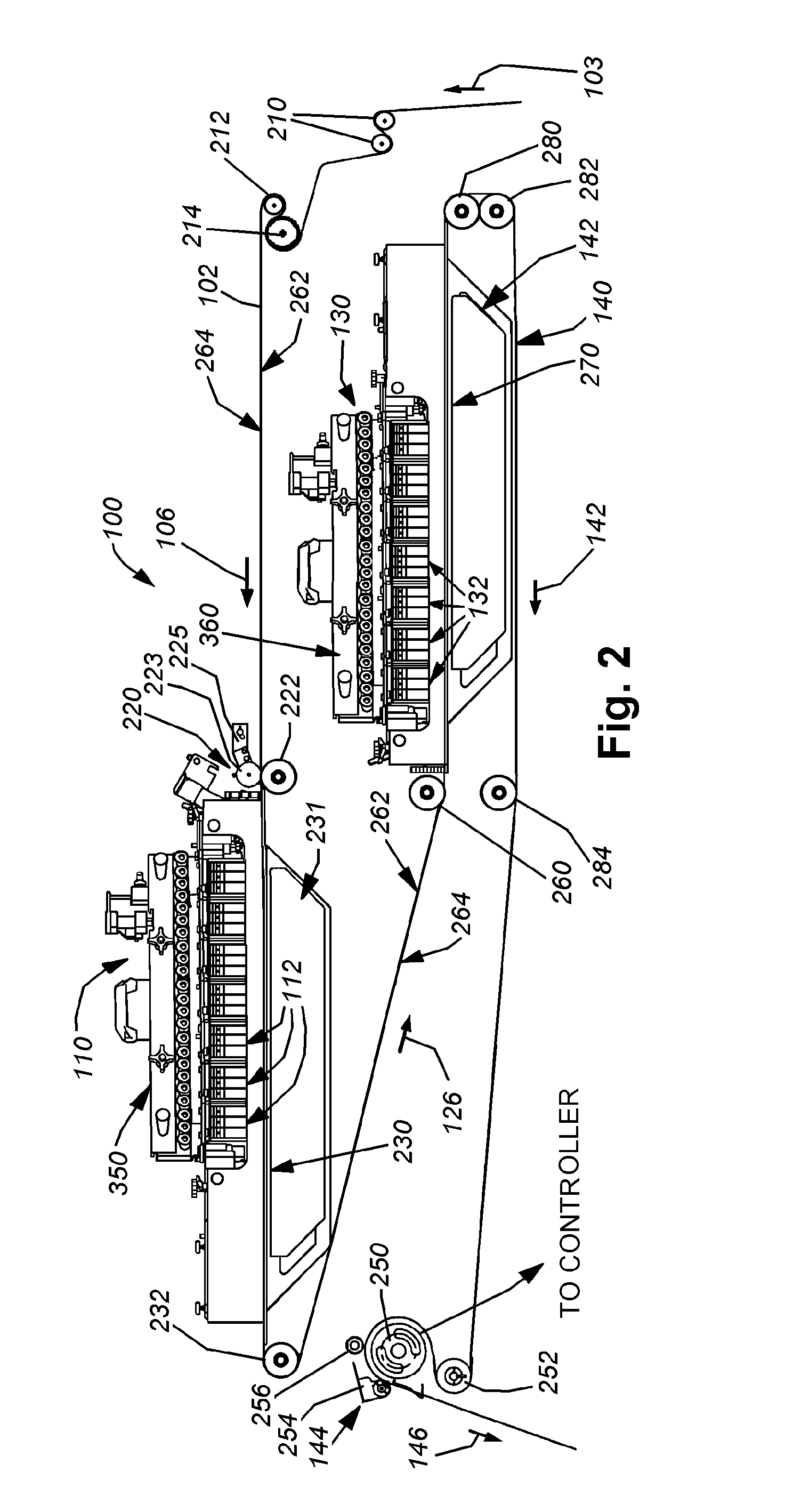
[0034]FIG. 1 illustrates a multi-ink-jet pen printer 100 adapted to feed a high-speed continuous web 102. The web 102 is fed (arrow 103) from a sensing loop 104 that is maintained at a predetermined size range by a driven roll stand (not shown) or other utilization device as the web 102 is drawn into the printer 100. The web 102 is directed downstream (arrow 106) to an upper printing fixed array 110 where the exposed top side of the web is printed via an array of interleaved ink-jet pens 112. As described further below, a group of pens is fed continuously by a respective manifold 114, 116 that receives bulk ink from each of a plurality of interconnected ink boxes / bags 120, 122, 124 and 126. The boxes / bags include one or more standard or custom ink colors that are adapted to be distributed through the ink-jet pens 112 via their electronically controlled nozzles.

[0035]The web 102 is fed (arrow 128) from the upper printing array 110 to a lower printing fixed array 130 that supports a s...


PUM


Abstract

This invention provides a system and method for printing continuous web and feeding ink to printing pens (or cartridges) that employs an array of interleaved ink-jet pens that are arranged to receive bulk ink through a manifold. The manifold and pens are mounted on a fixed array suspended over the web feed path. The manifold includes a plurality of self-sealing quick-disconnect couplings that each serve a discrete ink-jet pen. The pens lay down ink in a registered manner across the full width of the web. The pens are organized into two parallel, multi-pen arrays that are each diagonally oriented with respect to the feed direction. The feed path allows for duplex printing with a second web-side's array located on a lower level of the device, generally beneath the first-side's array. Duplex printing is facilitated due to its inherent length of the feed path. The printed part of the web is free of contact over predetermined lengths that ensure sufficient time for the drying of ink. Each pen is interconnected with a connection to a respective manifold that maintains a vacuum so as to prevent seepage of ink from the pen nozzles. The vacuum is maintained by a draw pump, while ink is continuously provided to the manifold via a float switch in a pressure regulator. The regulator is fed by a bulk ink supply using a feed pump. A check-valve standpipe on each manifold assists in removing any trapped air from the system, thus assisting in maintaining the vacuum.

Description

BACKGROUND OF THE INVENTION[0001]1. Field of the Invention[0002]This invention relates to devices for printing a continuous web and more particularly to devices that print using ink-jet pens.[0003]2. Background Information[0004]Electronic inline printing and processing of a continuous web of paper has become ubiquitous in recent years for a variety of purposes and industries. Such industries include publishing and “print-on-demand,” direct mail marketing, billing and the like. Typically, a web is directed from a large stand-mounted roll to one or more high-speed (typically greater than 100 pages per minute) electronic printers that deposit and fuse toner to the web. The web is then directed to further processing units that variously print, emboss, cut, sort, stack and fold the web, among other possible processes.[0005]It is often desirable to apply a color heading, logo, decoration or other device to the web either before or after the electronic printer has applied toner print. One ...

Claims


Application Information

Patent Timeline
Patent Type & Authority Patents(United States)
IPC IPC(8): B41J3/00
CPCB41J2/155B41J3/60B41J15/165B41J19/16B41J2202/21B41J29/02B41J2/175B41J2/1752B41J2/17523B41J2/18
Inventor SILVA, STEPHEN E.WOOD, PETER J.FISKE, JOHN M.ROZEA, CADMAN E.
Owner ROLL SYST
Why Eureka
Try Eureka