Optical transmitter/receiver module

a multi-wavelength, optical transmitter technology, applied in the direction of optical elements, multiplex communication, instruments, etc., can solve the problems of increasing the quantity of optical components, the limitations of the conventional system, and the complexity of the optical system, so as to reduce the total number of mounting steps, the number of structural elements is largely reduced, and the yield is high.

Inactive Publication Date: 2011-10-11
HITACHI LTD
View PDF10 Cites 32 Cited by
  • Summary
  • Abstract
  • Description
  • Claims
  • Application Information

AI Technical Summary

Benefits of technology

[0006]As previously described, needs for using laser light having a plurality of light emission wavelengths by being multiplexed with each other have been increased, in which these laser light sources have been utilized in projectors as a first need. However, in the above-described conventional type of laser projector, while the plural light sources having the different wavelengths are separately prepared, the individual optical systems are assembled. Also, in the conventional method, plural sets of the laser light are multiplexed with each other by employing the dichroic mirror. These conventional system and method have such a drawback that the optical systems are made complex, and the quantity of optical components is increased. As a result, there are some limitations when the conventional systems are made compact and the cost thereof is reduced.
[0007]As a consequence, an object of the present invention is to provide a multi-wavelength optical transmitter / receiver module which can be made compact and can be manufactured in high yield, while the multi-wavelength optical transmitter / receiver module is capable of largely reducing a total number of structural components and a total quantity of mounting steps of a system in various sorts of application fields, for instance, projectors, optical transmission communications, information processing appliances, biological measuring fields and so on.
[0012]In accordance with an embodiment of the present invention, with respect to a multi-wavelength transmitter module for transmitting a plurality of light having a plurality of wavelengths by a single optical axis, and also, a multi-wavelength receiver module, it is possible to provide such a compact optical module capable of realizing a high yield, while a total number of structural elements and a total number of mounting steps are largely reduced.
[0013]In accordance with the present invention, there are specific effects when systems are made compact and in low cost in various application fields such as data projectors, optical transmission communications, information processing appliances, and biological measuring devices with respect to the multi-wavelength transmitter module for transmitting the plurality of light having the plurality of wavelengths by the single optical axis, and also, the multi-wavelength receiver module, while the total number of structural elements and the total number of mounting steps can be largely reduced.

Problems solved by technology

These conventional system and method have such a drawback that the optical systems are made complex, and the quantity of optical components is increased.
As a result, there are some limitations when the conventional systems are made compact and the cost thereof is reduced.

Method used


Image

  • Optical transmitter/receiver module
  • Optical transmitter/receiver module
  • Optical transmitter/receiver module

Examples


first embodiment

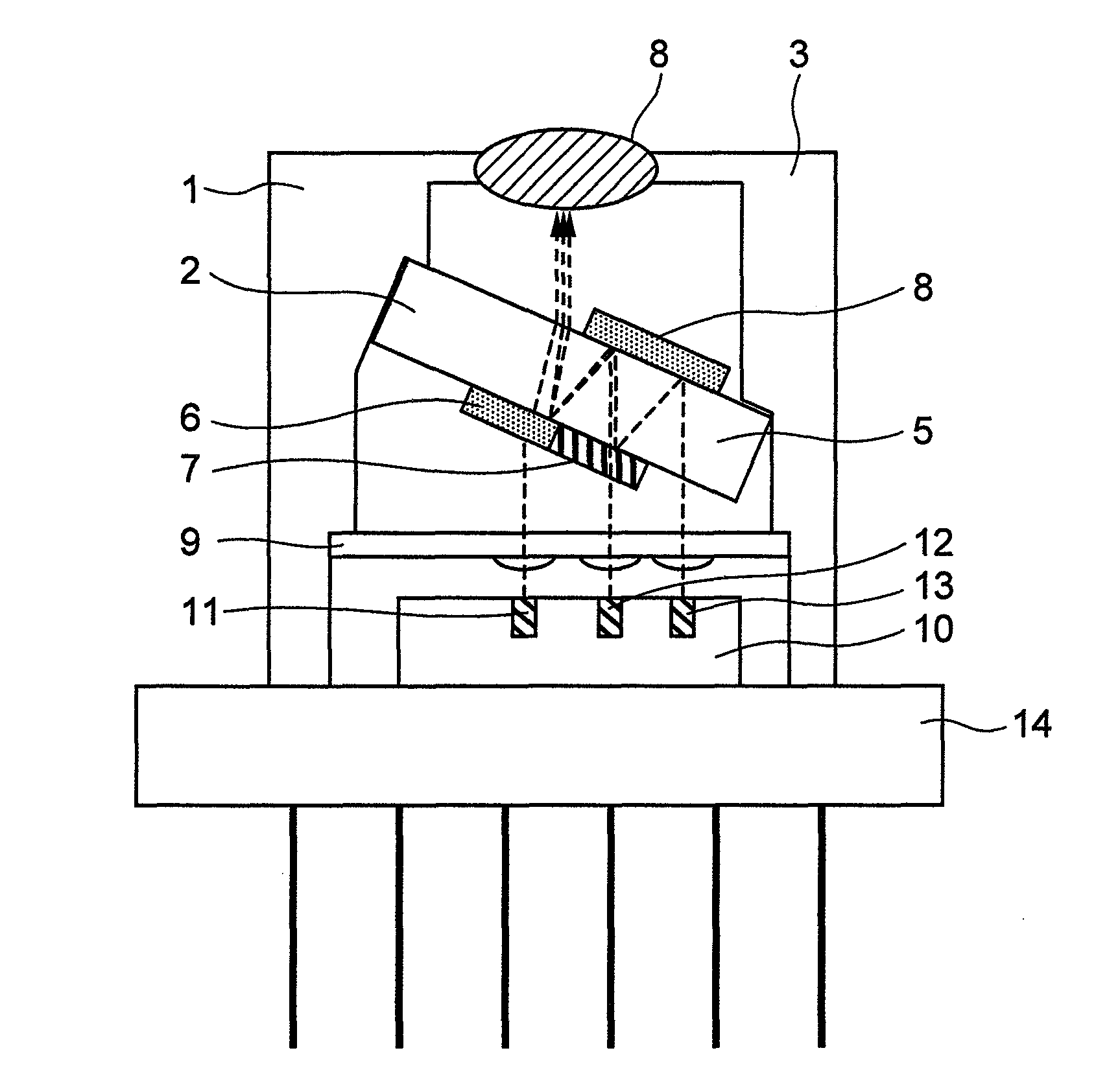
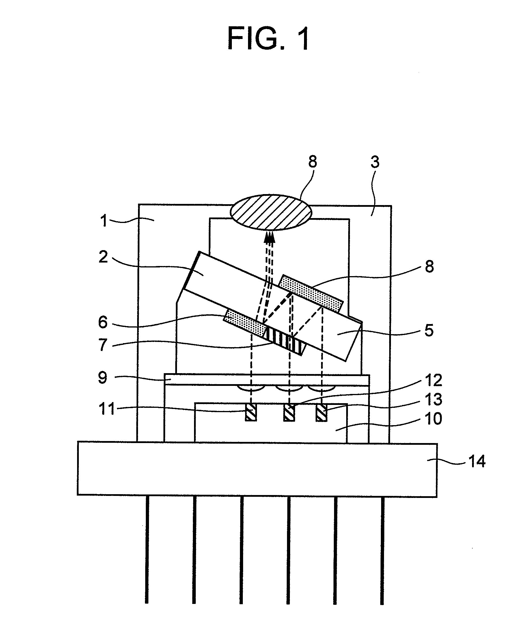
[0031]FIG. 1 and FIG. 3 are sectional views for showing an optical module according to a first embodiment of the present invention. FIG. 1 is such an example that the present invention has been applied to an optical transmitter module with employment of light sources of three primary colors (R, G, B primary colors).

[0032]FIG. 1 shows an example in which the optical transmission module has been mounted in a can package 1. That is, a stem 10 on which laser light sources 11, 12, 13 have been mounted has been mounted on a can stem 14, and an optical multiplexing / demultiplexing device 2 has been mounted on a can cap 3. FIG. 3 is a sectional view of the optical transmitter module shown in FIG. 1, as viewed at a rotation angle of 90 degrees from a view point of FIG. 1. A lens array 9 has been mounted just above laser elements. It is so assumed that waveforms of laser light emitted from the respective laser light sources 11, 12, 13 correspond to blue laser light (for instance, approximately...

second embodiment

[0035]FIG. 4 is a sectional view for showing an optical module according to a second embodiment of the present invention. The second embodiment is such an example that lens integrated type vertical emission LD elements 21, 22, 23 have been employed in light sources of respective wavelengths so as to construct the optical module. A lens integrated type vertical emission LD element corresponds to such an LD (laser diode) element which emits collimated laser light with respect to a substrate along a vertical direction.

[0036]It should be noted that although a basic function of the optical module according to the second embodiment is similar to the basic function of the first embodiment, since the lenses have been integrated on the LD elements 21, 22, 23, the above-described lens array 9 has not been assembled in the optical module.

third embodiment

[0037]FIG. 5A and FIG. 5B are sectional views for showing an optical module according to a third embodiment of the present invention. The optical module of this third embodiment is such an optical module that a light source can 30 where two laser diode elements having two red and blue wavelengths have been stored in a single can, and another light source can 31 for emitting green laser light having a single wavelength have been assembled in a single package. A structure of the light source can 30 having the two red and blue wavelengths is represented in FIG. 5B. The optical module of the above-described first embodiment has the function capable of multiplexing the laser light of three colors (three wavelengths) with each other, whereas the optical module of this third embodiment has the function capable of multiplexing only the laser light of the two colors (two wavelengths) with each other. In this third embodiment, as to the green color laser light source, the laser module 31 havi...


PUM


Abstract

An optical element mounting substrate where a plurality of light emitting elements have been mounted on the same plane, a lens array for collimating a plurality of light emitted from the plurality of light emitting elements, and a wavelength multiplexing / demultiplexing device are prepared. The wavelength multiplexing / demultiplexing device has typically mounted both a wavelength selecting filter and a mirror on front and rear planes of a transparent substrate. These three components are mounted within a package at a desirable angle position. Optical axes of respective wavelengths of the wavelength multiplexing / demultiplexing device are determined based upon a thickness and an angle of the light emitting element mounting substrate, and are arrayed on a straight line of a horizontal plane. As a consequence, if the respective light emitting elements are arranged on the optical axes which are exclusively determined by a design work, then optical multiplexing / demultiplexing operations can be carried out.

Description

INCORPORATION BY REFERENCE[0001]The present application claims priority from Japanese application JP2007-273302 filed on Oct. 22, 2007, the content of which is hereby incorporated by reference into this application.BACKGROUND OF THE INVENTION[0002]The present invention is generally related to an optical module. More specifically, the present invention is directed to a structure of a multi-wavelength optical transmitter module which optically multiplexes a plurality of laser light having a plurality of wavelengths with each other and then transmits the multiplexed laser light, and also, directed to a structure of an optical receiver module which optically demultiplexes such a light whose plural wavelengths have been multiplexed so as to receive the demultiplexed light.[0003]Semiconductor laser diode (LD) elements have been utilized in various sorts of technical fields such as information and telecommunication fields as compact light sources operable in higher efficiencies. Very recen...

Claims


Application Information

Patent Timeline
Patent Type & Authority Patents(United States)
IPC IPC(8): H04J14/02
CPCG02B6/4215G02B6/29367H04J14/02G02B6/293G02B6/42
Inventor HOSOMI, KAZUHIKOSAGAWA, MISUZUSUGAWARA, TOSHIKIAOKI, MASAHIRO
Owner HITACHI LTD
Why Eureka
Try Eureka