
Ceramic discharge vessel having an opaque zone and method of making same

a ceramic discharge vessel and opaque zone technology, applied in the manufacture of cold cathodes, electrode systems, electric discharge tubes/lamps, etc., can solve the problems of high emissivity, achieve greater wall temperature, increase wall temperature, and lower emissivity

Inactive Publication Date: 2011-10-18
OSRAM SYLVANIA INC
View PDF8 Cites 2 Cited by
  • Summary
  • Abstract
  • Description
  • Claims
  • Application Information

AI Technical Summary

Benefits of technology

[0005]At high temperatures, the emissivity (ε) of the ceramic material used to form the walls of the discharge vessel affects the wall temperature—the lower the emissivity, the greater the wall temperature. For example, forming arc tubes from yttria has been shown to increase wall temperatures by about 100° C. Yttria has a lower emissivity than polycrystalline alumina, about 0.1 compared to about 0.2 for PCA at about 1000° C. Conversely, a higher emissivity material will result in a lower wall temperature.
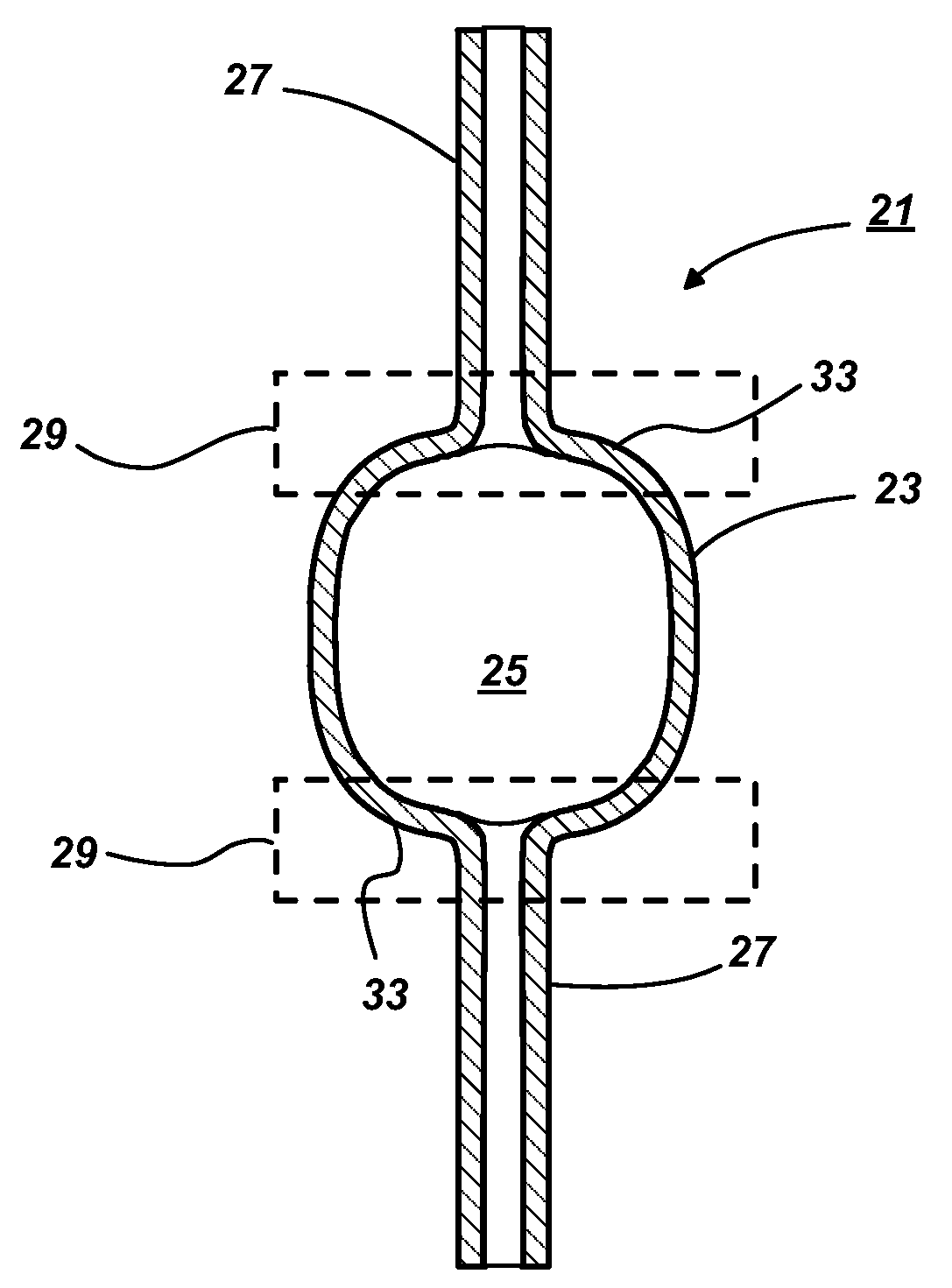
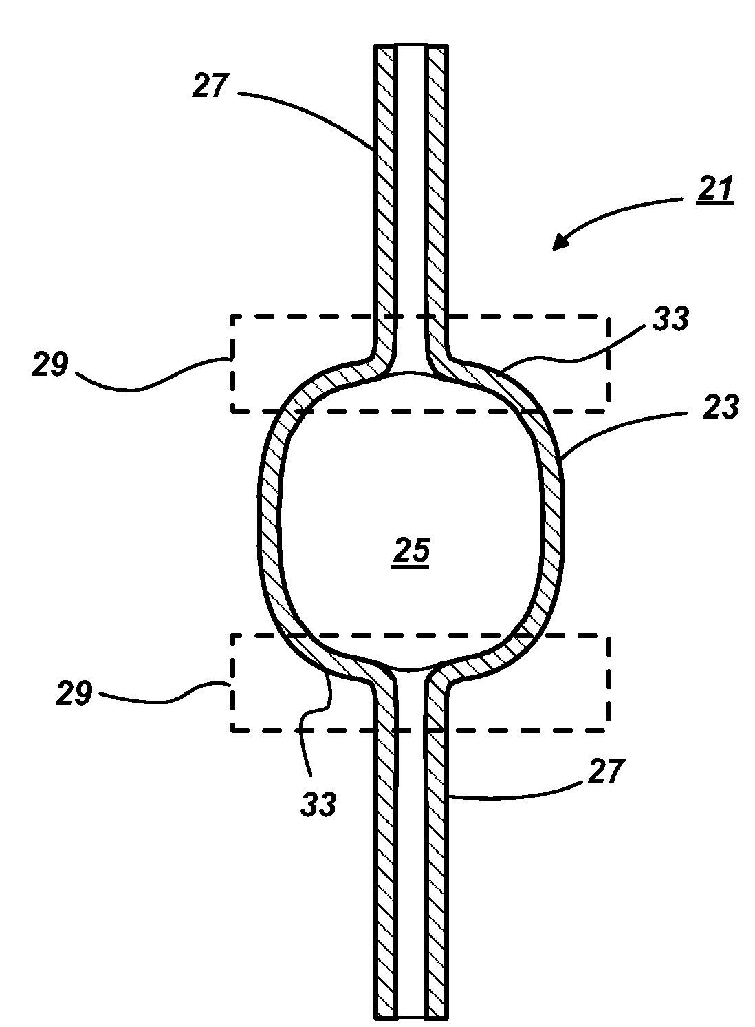
[0007]Although an opaque ceramic would not normally be thought of as desirable for a discharge vessel, the inventors have discovered that it is possible to form a reasonably well-defined opaque zone in a polycrystalline alumina discharge vessel. Because the location and extent of the opaque zone can be manipulated, the opaque zone may be designed to minimize any negative effect on the light output of the discharge vessel. The control over the placement of the opaque zone is achieved by forming a carbonaceous residue in a specific region of the discharge vessel prior to final sintering. During sintering, the carbonaceous material causes residual porosity in the sintered PCA. The residual pores inside the alumina grains scatter and absorb light causing opaqueness and higher emissivity. In the context of this invention, the term “opaque” means that incident light is scattered to such a degree that the PCA is no longer translucent. This manifests as a visually perceivable change in the appearance of the PCA which ranges from a frosted glass appearance to completely white.
[0008]The tailored opaque zone is intended to provide a cooler, localized temperature region in the discharge vessel to control the location of the metal halide condensate so as to produce a better lamp-to-lamp consistency and less spread in CCT and CRI over a lamp's operating life. This method is more effective and more durable than for example applying a high emissivity coating to the surface which can peel off discharge vessel as a result of thermal expansion mismatches and repeated heating and cooling cycles. Moreover, the opaque zone may be made at any location and of any configuration and size without redesigning the discharge vessel. Besides not requiring tooling changes, this has the added benefit of keeping the thermal mass of the discharge vessel the same as the original design so that the operating characteristics are relatively unchanged.

Problems solved by technology

The residual pores inside the alumina grains scatter and absorb light causing opaqueness and higher emissivity.

Method used


Image

  • Ceramic discharge vessel having an opaque zone and method of making same
  • Ceramic discharge vessel having an opaque zone and method of making same

Examples


examples

[0020]High purity (≧99.97% pure) Al2O3 powder was used as the starting powder. The powder contained finely divided Al2O3 particles with a crystallite size of 0.05 μm, a mean specific surface area of 30-6 m2 / g, and an average particle size of 0.45 μm. The sintering aids were based on the MgO+ZrO2+Y2O3 system. The alumina powder was mixed with an organic binder to form the discharge vessel shape. Prefiring of the green shapes was conducted at 850-1350° C. in air to remove the organic binder.

[0021]In order to form the opaque zones, an aqueous solution containing 10 weight percent (wt. %) polyvinyl alcohol was painted onto the targeted area of the air-prefired discharge vessels using a small brush. The painted discharge vessels were placed in vacuum desiccator to allow the 10 wt. % polyvinyl alcohol-water solution to soak into the alumina and dry. These steps were repeated three times to fully impregnate the wall of the prefired discharge vessel. The painted parts were then placed verti...


PUM

PropertyMeasurementUnit
weight percentaaaaaaaaaa
temperatureaaaaaaaaaa

Abstract

An opaque zone in the polycrystalline (PCA) discharge vessel of a high intensity discharge lamp may be made by creating residual pores in predetermined regions of the final-sintered discharge vessel. The control over the placement of the opaque zone is achieved by forming a carbonaceous residue in a specific region of the discharge vessel prior to final sintering. During sintering, the carbonaceous material causes residual porosity in the sintered PCA. The higher emissivity of the opaque PCA provides localized cooling in order to provide more control over the condensate behavior in the discharge vessel.

Description

TECHNICAL FIELD[0001]This invention relates to ceramic discharge vessels for high intensity discharge (HID) lamps, and, more particularly, to polycrystalline alumina (PCA) discharge vessels for metal halide lamps.BACKGROUND OF THE INVENTION[0002]Metal halide discharge lamps are favored for their high efficacies and high color rendering properties which result from the complex emission spectra generated by their rare-earth chemistries. Particularly desirable are ceramic metal halide lamps which offer improved color rendering, color temperature, and efficacy over traditional metal halide lamps having quartz discharge vessels. This is because ceramic discharge vessels can operate at higher temperatures than their quartz counterparts and are less prone to react with the various metal halide chemistries.[0003]Most commercial ceramic metal halide lamps contain a fill comprising an amount of mercury and a complex combination of metal halides, particularly iodides. The fill chemistries of m...

Claims


Application Information

Patent Timeline
Patent Type & Authority Patents(United States)
IPC IPC(8): H01J17/49H01J17/16H01J17/00H01J17/20
CPCH01J9/247H01J61/302
Inventor WEI, GEORGE C.TARRY, CHRISTOPHER A.HUETTINGER, ROLAND
Owner OSRAM SYLVANIA INC
Learn More