Azimuth angle measurement

a technology of azimuth angle and measurement method, applied in the field of scatterometry, can solve the problems of error in the reported shape, not being able to accurately measure the angle, etc., to improve accuracy and tool matching, extend ocd technology, and improve ocd sensitivity.

Active Publication Date: 2011-10-18
KLA TENCOR TECH CORP
View PDF4 Cites 42 Cited by
  • Summary
  • Abstract
  • Description
  • Claims
  • Application Information

AI Technical Summary

Benefits of technology

[0074]Optical azimuth measurement results obtained in accordance with embodiments of the present invention may be used to determine the correction necessary to reduce the optical azimuth angle to meet specifications. The optical azimuth angle result may be used as a calibration value or correction factor in OCD scatterometry signal analysis to improve accuracy and tool matching.
[0075]Future developments to improve OCD sensitivity and extend OCD technology to smaller feature sizes may increasingly rely on azimuth accuracy. Azimuth angle error is a significant part of the OCD scatterometry tool matching differences and resulting accuracy errors. Measuring, reducing, calibrating and correcting for this azimuth error will enable OCD systems to meet tighter tool matching requirements and accuracy specifications.

Problems solved by technology

However this angle is not perfectly controlled and is not measured.
If the theoretical angle of the plane of incidence does not match the actual angle of the plane of incidence, the theoretical spectrum will not match the measured spectrum, resulting in an error in the reported shape.
However, in practice, this is generally not the case.
Unfortunately, an image alignment system does not measure the optical azimuth angle φO between the plane of incidence or plane of detection and the x-y stage axes or any feature on the wafer.
Such azimuth measurement techniques may suffer from certain disadvantages.
Another disadvantage of the previous azimuth measurement systems is that they cover only the incident beam and cannot take into account the optics on the detection side.

Method used


Image

  • Azimuth angle measurement
  • Azimuth angle measurement
  • Azimuth angle measurement

Examples


Embodiment Construction

[0022]Although the following detailed description contains many specific details for the purposes of illustration, anyone of ordinary skill in the art will appreciate that many variations and alterations to the following details are within the scope of the invention. Accordingly, the exemplary embodiments of the invention described below are set forth without any loss of generality to, and without imposing limitations upon, the claimed invention.

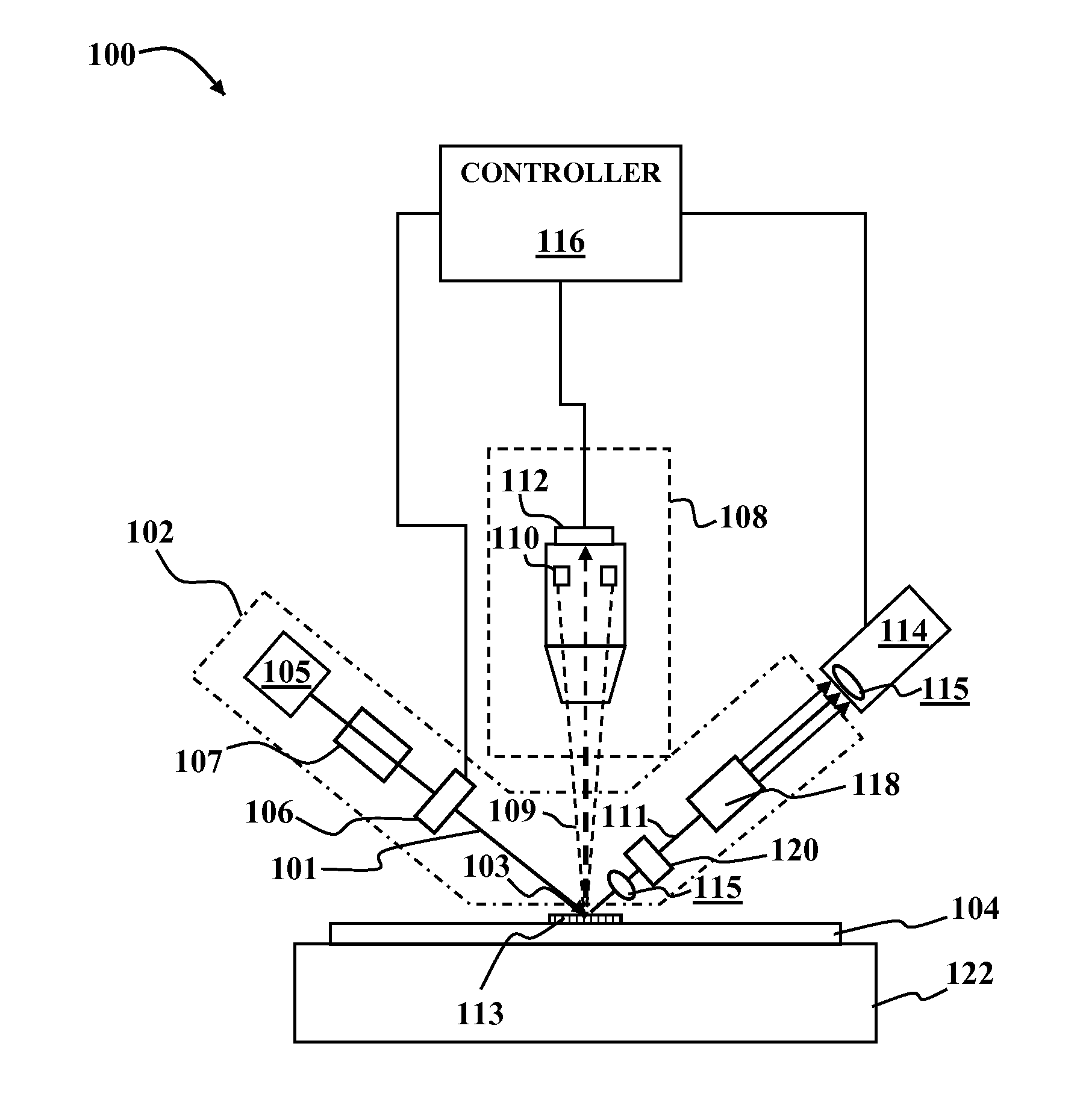
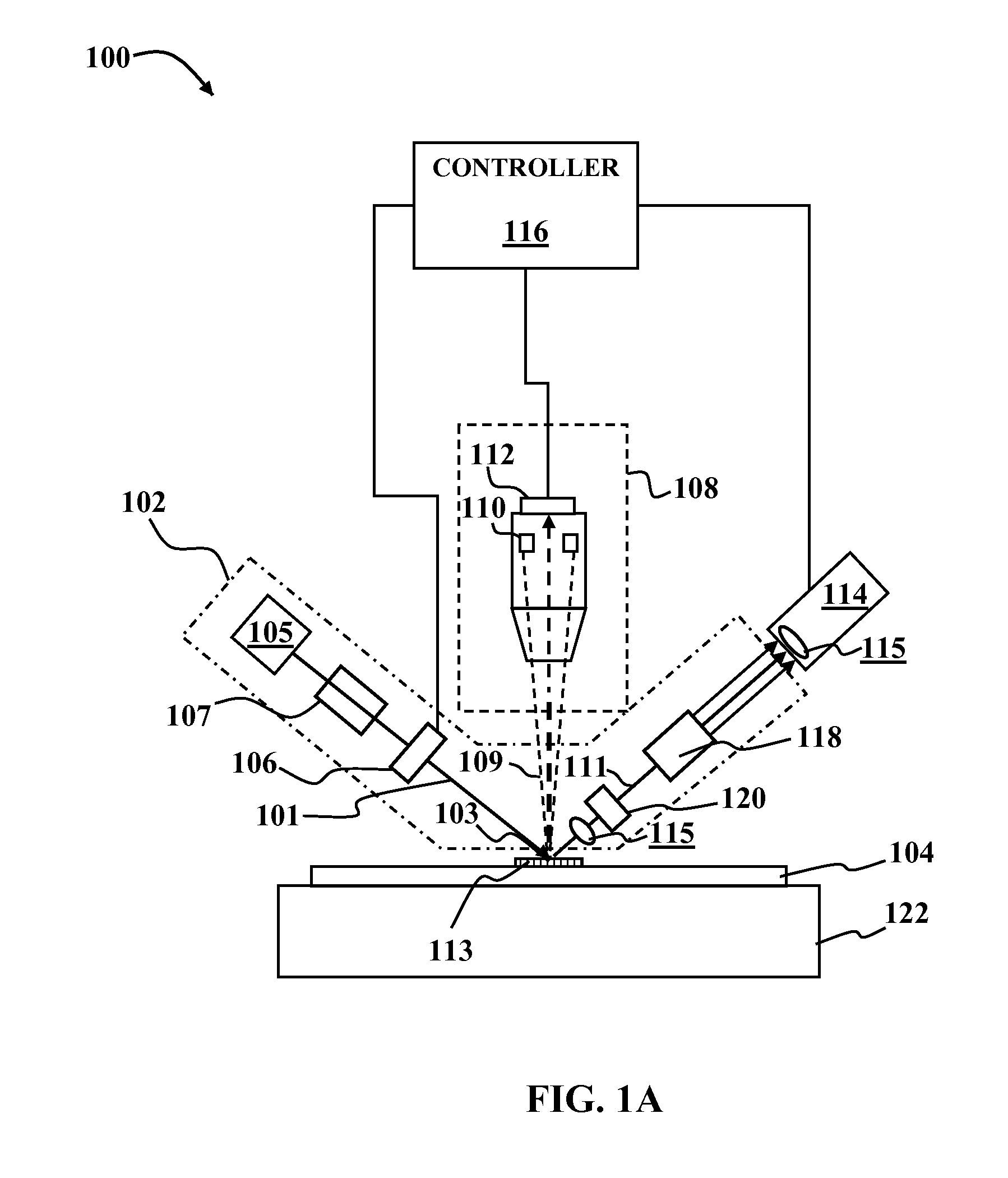
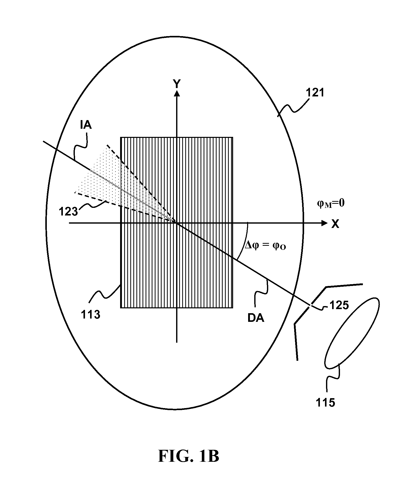
[0023]According to embodiments of the present invention, azimuth angle between a plane of a detected scatterometer beam and a periodic structure that scatters the detected beam may be measured by analyzing properties of the resulting measured scatterometer signal. The error in optical azimuth angle φO may significantly impact the measurement accuracy. For certain samples an optical azimuth angle error δφO as small as 0.1 degree may cause the system to fail in meeting tool-to-tool matching specifications.

[0024]One type of scatterometry techni...


PUM


Abstract

Methods and apparatus for measuring an optical azimuth angle φO of a substrate relative to a plane of detection in scatterometry tools are disclosed. A grating target on a stage of a scatterometry tool may be illuminated and positions of the resulting diffraction orders may be observed. The optical azimuth angle may be determined from the positions of the diffraction orders. Alternatively, polarization-dependent signals of radiation scattered from a line grating may be measured for equal and opposite polarization angles +A and −A. A combination signal may be computed from the polarization-dependent signals obtained at +A and −A and a property of the combination signal may be calculated for several mechanical Azimuth angles φM. A relationship between the optical azimuth angle φO and the mechanical azimuth angle φM may be determined from a behavior of the property as a function of mechanical azimuth angle φM.

Description

PRIORITY CLAIM[0001]This application claims the benefit of priority of commonly assigned U.S. Provisional Patent Application No. 61 / 024,510, filed Jan. 29, 2008, the entire disclosures of which are incorporated herein by reference.FIELD OF THE INVENTION[0002]This invention generally relates to scatterometry and more particularly to calibration of optical azimuth angle in scatterometry.BACKGROUND OF THE INVENTION[0003]For a number of industrial applications, it is useful to determine the surface metrology of samples such as thickness of thin films, their refractive indices and the profile parameters of surface features such as grating on semiconductor wafers. A number of metrology tools are now available for performing optical measurements on semiconductors. Such tools can include scatterometers, such as spectroscopic reflectometers, angle-resolved reflectometers, and angle-resolved ellipsometers, and spectroscopic ellipsometers. Such scatterometry techniques have been extensively us...

Claims


Application Information

Patent Timeline
Patent Type & Authority Patents(United States)
IPC IPC(8): G01J4/00
CPCG01B11/26G01N21/211
Inventor KRISHNAN, SHANKARZHOU, HAIXINGWANG, HAIMINGLIDSKY, DAVIDMIEHER, WALTER DEAN
Owner KLA TENCOR TECH CORP
Why Eureka
Try Eureka