Minimal-temperature-differential, omni-directional-reflux, heat exchanger

a heat exchanger and omni-directional technology, applied in the field of heat pipes, can solve the problems of large relative temperature differentials, inability to easily control wicks, and dynamic activity of heat exchange systems that do not necessarily lend themselves to optimization, and achieve the effect of promoting the flow of working fluids

Inactive Publication Date: 2011-10-25
UTAH STATE UNIVERSITY
View PDF34 Cites 16 Cited by
  • Summary
  • Abstract
  • Description
  • Claims
  • Application Information

AI Technical Summary

Benefits of technology

[0032]Thus, a vapor may pass between the plates unimpeded, and unrestricted by the actual walls of the channel. Meanwhile, the presence of the pedestals formed by the intersecting channels may sufficiently form a slower boundary layer region for the vapor phase such that the vapor phase will not entrain any substantial amount of the liquid in the channels below the open “tops” of the pedestals.
[0036]An apparatus will typically deliver heat to a comparatively cooler location at which a vapor phase of the working fluid will condense proximate a wall thereof, and typically at an inner surface of the substrate, to become the liquid phase of the working fluid. Supporting and promoting capillary action is therefore an advantage of this invention. Channels with their comparatively small dimensions are sized to render surface tension forces a significant transport mechanism due to capillary action. Comparatively cooler areas will then accumulate liquid, and transfer it back from the source or origin of the liquids toward the drying and comparatively hotter portion of the channel or the assembly.
[0038]It is not required that the floor of all the channels be in a single plane, nor that every channel be exactly of the same width or wall height. Nevertheless, the presence of an exactly regular configuration such as exactly parallel channels on an exactly repeating pitch, with cross-channels arranged orthogonally thereto with exactly the same dimensions, provides a high degree of isotropy extremely valuable in eliminating any penalty for a liquid or vapor taking any direction or path of choice.
[0044]Nevertheless, if a heat source is in thermal contact with a lower assembly while a heat sink is in contact with an upper assembly, a benefit may exist in providing two substrates each provided with channels. These bases placed opposite one another may or may not be minor-images of one or another. Likewise, if an assembly in accordance with the invention is operated in a vertical orientation, wherein the “plane” of pedestal tops is vertically oriented, and orienting the comparatively hotter location of the assembly lower, and the comparatively cooler location of the assembly higher, may provide certain benefits of gravity for promoting flows of the working fluid.

Problems solved by technology

Thus, vapor gaps cause very large relative temperature differentials to exist between the hot wall of a heat pipe, and the liquid surface of a working fluid in the wick.
However, wicks cannot be so easily controlled, and the dynamic activity of a heat exchange system does not necessarily lend itself to an optimization of a wick thickness.
All systems have bottlenecks.
Very few systems are optimized to operate at their perfect conditions at all locations within the system, and particularly not at all times and under all conditions.
Thus, vapor flows may be obstructed or restricted due to the fluid dynamics of their passage along some conduit or enclosed path.
Likewise, the flow of liquids may be restricted by the fluid dynamics of the liquid in its environment, as well as various obstructions along the path including turns, blockages, and the like.

Method used


Image

  • Minimal-temperature-differential, omni-directional-reflux, heat exchanger
  • Minimal-temperature-differential, omni-directional-reflux, heat exchanger
  • Minimal-temperature-differential, omni-directional-reflux, heat exchanger

Examples


Embodiment Construction

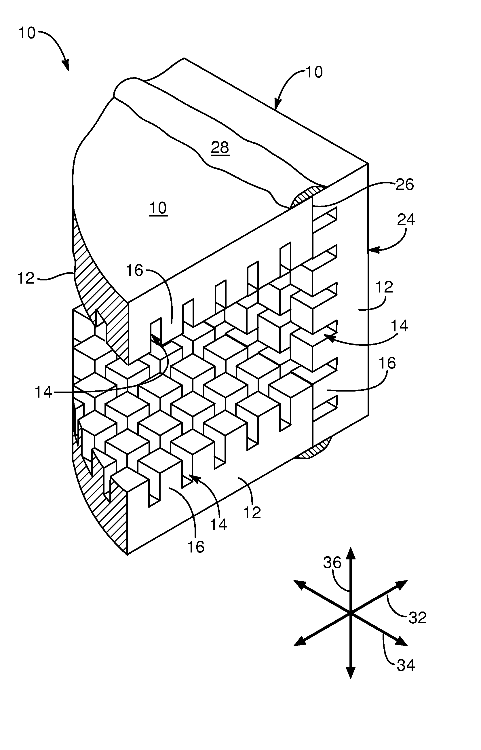
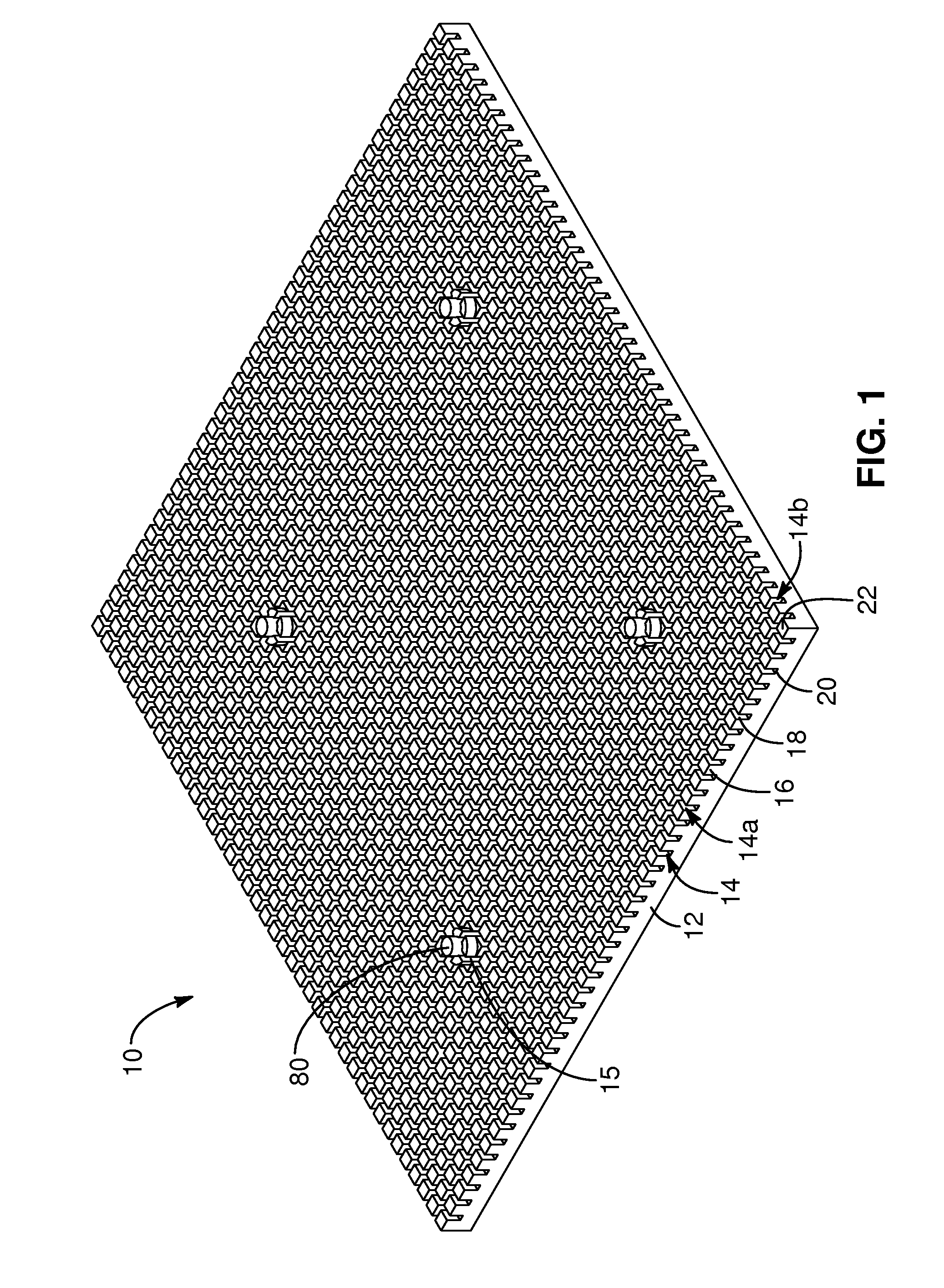
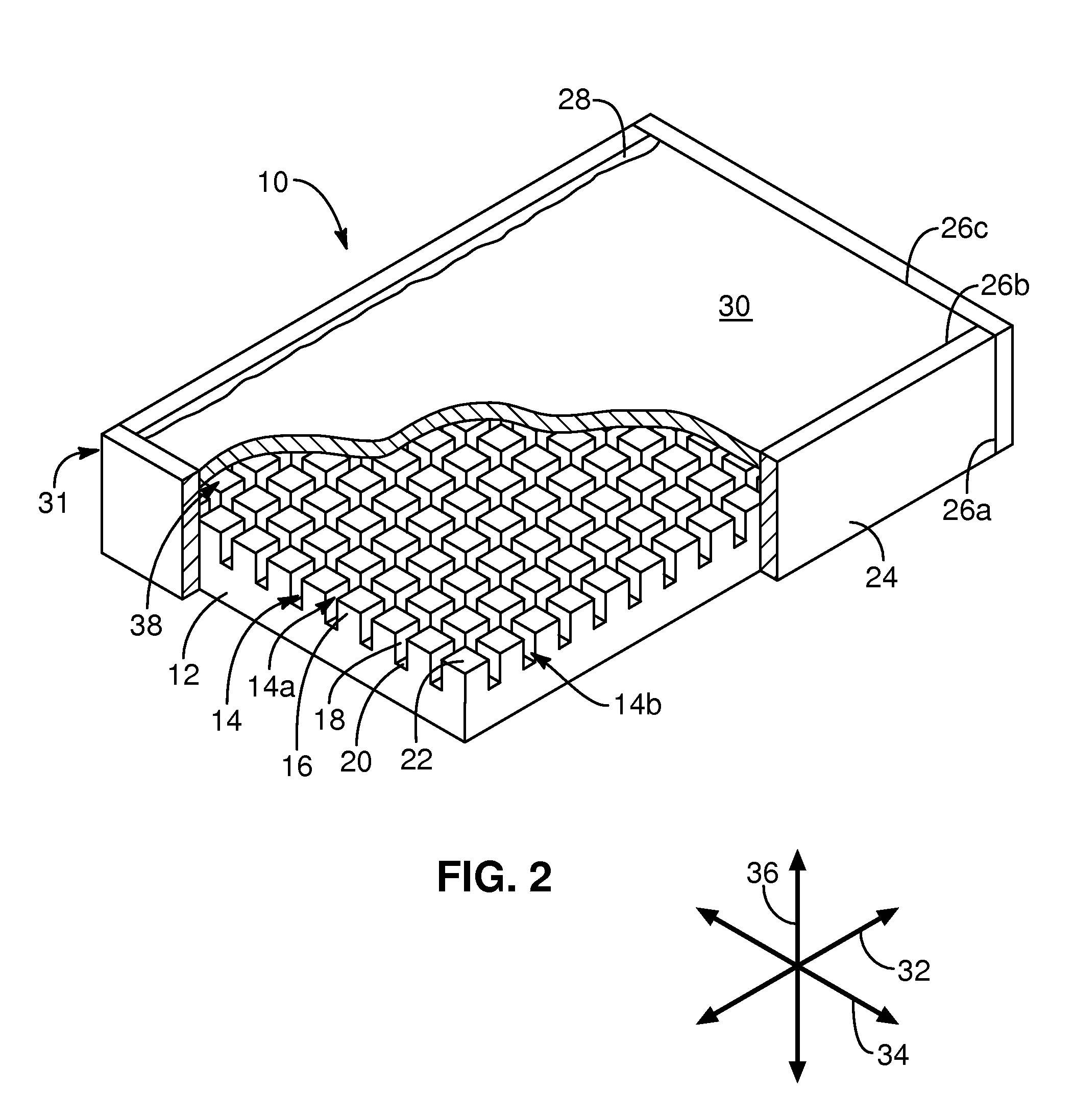
[0067]Referring to FIGS. 1-4, an apparatus 10 in accordance with the invention may be formed to have a base 12 formed of a material suitable for heat transfer. Typical materials may be metals such as aluminum, copper, steel, and the like. In certain embodiments, materials of comparatively lower thermal conductivity such as polymers, polymer composites, and carbon-carbon composites have successfully been used. Aluminum has been found to be an excellent heat transfer material. Likewise, gold and precious metals have excellent heat transfer characteristics, in spite of their exorbitant costs for most applications. In certain embodiments, various varieties of steel and other metals are also suitable.

[0068]In certain embodiments, applicants have manufactured plastics having suitable heat transfer characteristics if view of the close proximity of the internal surfaces, at which phase changes occur, to the external surfaces in contact with the heat source or sink. This direct wetting of in...


PUM


Abstract

A substrate formed of a suitable conductive-heat-transfer material is formed with small channels of a size selected to provide surface tension forces dominating a motion of a liquid-phase working fluid. A space above the channels of the substrate provides comparatively unobstructed space for the transport motion of a vapor phase of the working fluid effecting a heat-pipe effect in a multi-dimensional device. Channels may typically be formed in an orthogonal grid providing capillary return of liquids from a comparatively cooler condensation region to a comparatively warmer evaporation region, without any wicks other that the adhesion of the liquid phase working fluid to the vertices of the channels. Interference between the boundary layers of the liquid phase and the vapor phase of the working fluid are minimized by the depth of the channels, and the pedestals formed by the channel walls. Extremely small temperature differentials are thereby achieved between an outer surface of the substrate and an inner surface of the substrate when the liquid phase floods the substrate.

Description

RELATED APPLICATIONS[0001]The present application claims the benefit of co-pending U.S. Provisional Patent Application Ser. No. 60 / 836,901, filed Aug. 9, 2006 for CHANNEL-PANEL HEAT TRANSFER DEVICE and co-pending U.S. Provisional Patent Application Ser. No. 60 / 861,583 filed Nov. 29, 2006 for MINIMAL-TEMPERATURE-DIFFERENTIAL, ISOTROPIC-FLOW, REFLUX HEAT EXCHANGER.BACKGROUND[0002]1. The Field of the Invention[0003]This invention relates to heat pipes, and more particularly to two-dimensional flows of liquid and vapor through wickless channels to maximize flows of vapor and liquid, minimize the effect of obstructions and hot spots, and minimize temperature differentials between a source of heat and a heat sink.[0004]2. The Background Art[0005]Heat exchangers are well documented throughout engineering literature as mechanisms for exchanging heat between media, moving heat from one place to another, and other means for energy transport. Typically, heat is transferred by conduction, conve...

Claims


Application Information

Patent Timeline
Patent Type & Authority Patents(United States)
IPC IPC(8): F28D15/04
CPCF28D15/046F28F13/187F28D15/0233
Inventor BATTY, J. CLAIRJENSEN, SCOTT M.
Owner UTAH STATE UNIVERSITY
Why Eureka
Try Eureka