Reference voltage generator

a reference voltage and generator technology, applied in the direction of automatic control, process and machine control, instruments, etc., can solve the problems of overshooting of output voltage vout and delay in stabilization, and achieve the effect of reducing noise of reference voltage source and disturbance, precise reference voltage and short tim

Inactive Publication Date: 2011-10-25
PANASONIC CORP
View PDF10 Cites 12 Cited by
  • Summary
  • Abstract
  • Description
  • Claims
  • Application Information

AI Technical Summary

Benefits of technology

[0012]The method of the second conventional example seemingly is advantageous in that, even when the time constant is not sufficiently small, the stabilization time can be reduced infinitely by setting the set value of the hysteresis comparator to be small. However, the fact is that, due to an offset voltage of the hysteresis comparator that hardly can be made to become 0 V, an inputted voltage difference is shifted to a value in the neighborhood of the set value.
[0014]Moreover, when the switch is formed of a semiconductor element such as a MOS or the like, due to a charge injection effect in which electric charges accumulated in a channel are discharged when turning off, an electric current flows, though for a short time, into the capacitor of the low-pass filter even after the switch has been switched off, so that a voltage becomes even higher. Whether the output voltage Vout is insufficient or excessive with respect to a steady state voltage, an operation of gradually approximating to the steady state voltage occurs with the time constant RC, resulting in a delay in the stabilization.
[0016]With the foregoing in mind, it is an object of the present invention to provide a reference voltage generator that is capable of charging a capacitor of a low-pass filter for reducing noise rapidly so that an output voltage can be stabilized rapidly.
[0020]According to each of the reference voltage generators of the above-described configurations, during a predetermined time period immediately after power-on, a capacitor C of the low-pass filter is charged rapidly by means of the first voltage buffer circuit or the switching elements. Thus, noise of the reference voltage source and disturbance can be reduced, and at power-up, a precise reference voltage can be attained in a short time.

Problems solved by technology

Furthermore, even if the offset voltage can be made to be 0 V by calibration or correction, a switching off of the switch tends to be delayed due to the limited response of the hysteresis comparator, so that an excessive voltage is applied to the power source voltage side, leading to the occurrence of overshoot of the output voltage Vout.
Whether the output voltage Vout is insufficient or excessive with respect to a steady state voltage, an operation of gradually approximating to the steady state voltage occurs with the time constant RC, resulting in a delay in the stabilization.

Method used


Image

  • Reference voltage generator
  • Reference voltage generator
  • Reference voltage generator

Examples


first embodiment

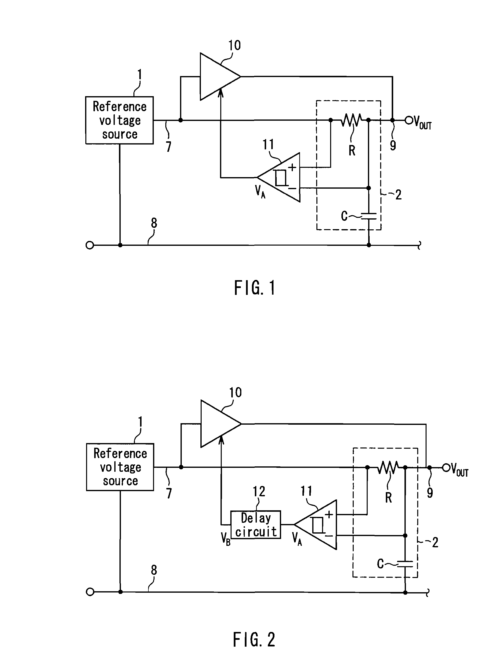
[0035]FIG. 1 is a circuit diagram showing a configuration of a reference voltage generator according to a first embodiment of the present invention. A low-pass filter 2 is connected to an output node 7 of a reference voltage source 1 that generates a direct-current voltage that is used as a reference. The low-pass filter 2 is a RC primary filter that in the simplest form is a low-pass filter composed of a resistor R and a capacitor C connected in series between the output node 7 and a ground terminal 8 of the reference voltage source 1. A connection point between the resistor R and the capacitor C is an output node 9 of the low-pass filter 2, at which a voltage obtained by smoothing an output voltage of the reference voltage source 1 is generated. This configuration reduces noise generated by the reference voltage source 1 and the influence of an external disturbance upon the reference voltage source 1.

[0036]An input terminal of a first voltage buffer circuit 10 further is connected...

second embodiment

[0048]FIG. 2 is a configuration diagram of a reference voltage generator according to a second embodiment of the present invention. This reference voltage generator has a revised configuration of the reference voltage generator according to the first embodiment shown in FIG. 1, in which the output VA of the hysteresis comparator 11 is inputted to the first voltage buffer circuit 10 via a delay circuit 12. Based on a control signal VB delayed by a predetermined time period by the delay circuit 12, a first voltage buffer circuit 10 is controlled.

[0049]In the first embodiment, a time required from the time when the output impedance of the first voltage buffer circuit 10 is switched to the high impedance state until the time when the voltage of the output node 9 reaches the steady state is determined by the time constant of the low-pass filter 2. The smaller the second set value of the hysteresis comparator 11, the more the time required for the steady state to be reached is reduced. Ho...

third embodiment

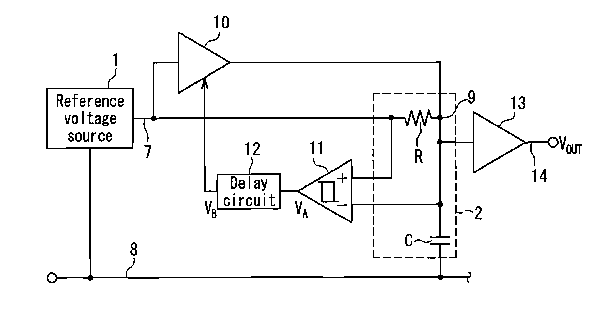
[0054]FIG. 3 is a configuration diagram of a reference voltage generator according to a third embodiment. This embodiment has a revised configuration of the reference voltage generator shown in FIG. 2, in which the output node 9 of a low-pass filter 2 is connected to an input terminal of a second voltage buffer circuit 13, and an output terminal 14 of the second voltage buffer circuit 13 is an output terminal of the reference voltage generator.

[0055]This configuration allows an output to be outputted to the output terminal 14 at a low output impedance. Most of loads are resistive or capacitive types and thus, in some cases, cannot be driven sufficiently with an output impedance of a low-pass filter 2. In such cases, impedance conversion is performed by the second voltage buffer circuit 13, thereby allowing the above-described problem to be solved.

[0056]In the case where conversion of an output voltage value is necessary, it is possible to use, in place of the second voltage buffer c...


PUM


Abstract

A reference voltage generator includes: a reference voltage source 1 that generates a direct-current voltage that is used as a reference; a low-pass filter 2 that is connected to an output node of the reference voltage source; a first voltage buffer circuit 10 with an input terminal to which the output node of the reference voltage source is connected and an output terminal to which an output node of the low-pass filter is connected, which has a voltage gain of one time; and a hysteresis comparator 11 with one input terminal to which the output node of the reference voltage source is connected and an other input terminal to which the output node of the low-pass filter is connected. At start-up, during a time period in which a voltage difference between an output of the reference voltage source and an output of the low-pass filter exceeds a predetermined value, an output impedance of the first voltage buffer circuit is controlled based on an output signal of the hysteresis comparator. At start-up, the low-pass filter that reduces noise is charged with a low impedance rapidly, and thus an output voltage can be stabilized rapidly.

Description

BACKGROUND OF THE INVENTION[0001]1. Field of the Invention[0002]The present invention relates to a reference voltage generator, and particularly to an improved configuration in which a capacitor of a low-pass filter for reducing the noise of a reference voltage source is charged rapidly so that an output voltage is stabilized rapidly.[0003]2. Description of Related Art[0004]A configuration in which a low-pass filter is provided additionally downstream of a reference voltage source in order to reduce the noise of the reference voltage source is disclosed in, for example, JP 8(1996)-272461 A (first conventional example). FIG. 7 shows a circuit according to this first conventional example. In the configuration shown in FIG. 7, a low-pass filter 2 composed of a resistor R and a capacitor C is connected to a point A to which a voltage of a reference voltage source 1 is outputted so as to reduce noise in a voltage outputted to a point B. Hereinafter, a resistance value of the resister R i...

Claims


Application Information

Patent Timeline
Patent Type & Authority Patents(United States)
IPC IPC(8): G05F1/10
CPCG05F1/56G05F3/16
Inventor KUME, TOMOHIRO
Owner PANASONIC CORP
Why Eureka
Try Eureka