Method for producing polarisation filters and use of polarisation-sensitive photo-sensors and polarisation-generating reproduction devices

a polarisation filter and photosensor technology, applied in the direction of optical radiation measurement, instruments, polarising elements, etc., can solve the problem of little contrast in structures of the order of 100 nm, and achieve the effect of less weight, reduced resolution and greater compactness

Active Publication Date: 2011-10-25
GRAU GUNTER
View PDF20 Cites 12 Cited by
  • Summary
  • Abstract
  • Description
  • Claims
  • Application Information

AI Technical Summary

Benefits of technology

[0032]Said above discussed problem is solved also by a fourth disclosure of the present invention by means of apparatus measuring light polarization, comprising at least one sensor element which is fitted with lithographically made grating structures, being configured above the sensor element in at least one fabrication plane and / or wiring plane, of which the geometric structure and orientation was determined beforehand by mask data design in a manner that a polarization sensor is constituted as one physical unit, where preferably only the conventional structure sizes of integrated circuit designs, and its conventional fabrication steps, are used. The use of conventional steps in manufacturing integrated circuits, as well being restricted to them, lead to the possibility manufacturing integrated circuits with polarization sensitive optic sensors absent any additional effort. Production and alignment of the filter relative to the sensor takes place with the same high accuracy as for the remainder of the integrated circuit. The structure of the polarization filter is defined by mask data which also control the remaining manufacture. The assumption here is, essentially, that the smallest structures can be made be smaller than the wavelength to be polarized. The grating period with parallel strips should be significantly smaller than half the wavelength. The filters in the form of grating structures can be produced lithographically in at least one fabrication plane and / or wiring plane of which the geometric structure and orientation was predetermined during the drafting of mask data, preferably only the structure sizes allowed when planning the integrated circuits being allowed (the so-called design rules). As regards present-day commonplace structural sizes of 130 nm or less, significant polarization can be attained in the IR range of light. If a contrast ratio of 1:3 can be attained in a 130 nm technology with a single layer filter, for instance at a wavelength of 1.5 microns (μ), then, to a first approximation, the contrast is raised to a higher power when several filter layers are arrayed in series in accordance with the concatenation of the transfer functions. When making optimal use of all finely structurable polycrystalline silicone and metallization planes, high contrast ratios can be attained in standard technologies without entailing even one additional processing step. Using this method, and besides saving the expense of separately manufacturing a filter sheet, it is possible to substantially raise the number of sensors per area as a result of which more information is available in the same or less space. In the case of a specially selected geometry of the stacked filter planes or at specified wavelengths, resonance effects may be advantageously exploited to further increase contrast.
[0055]At least one polarization sensor, one transparent medium and one polarized light source are used in a further advantageous embodiment mode of the apparatus of the present invention, said polarized light after passing through the transparent medium—which preferably allows using the Faraday or the Kerr effect—being detected by the polarization sensor. Such apparatus is appropriate to measure strong static and dynamic magnetic or electric fields and merely requires that the transparent medium be defined as to its shape, but requiring no electrical or magnetic components in the field to be measured. This design offers various advantages relative to Hall generators or measuring coils, in particular in rapidly changing fields.

Problems solved by technology

However only little contrast is available in structures of the order of 100 nm.

Method used


Image

  • Method for producing polarisation filters and use of polarisation-sensitive photo-sensors and polarisation-generating reproduction devices
  • Method for producing polarisation filters and use of polarisation-sensitive photo-sensors and polarisation-generating reproduction devices
  • Method for producing polarisation filters and use of polarisation-sensitive photo-sensors and polarisation-generating reproduction devices

Examples


example 1

Manufacture, Restricted to the Manufacturing Steps for Making an Integrated Circuit, of Structured Polarization Filters Using Photolithography

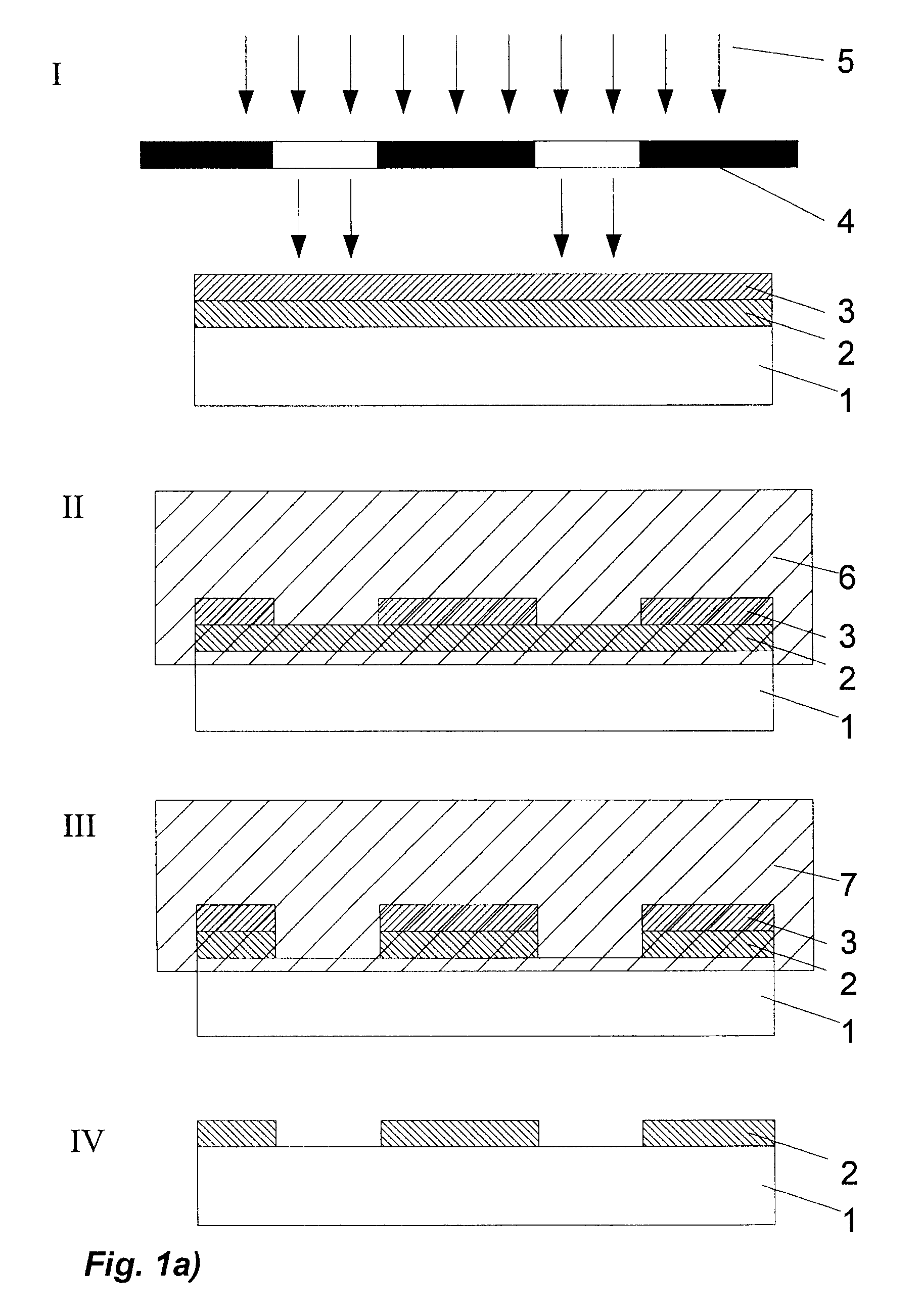
[0057]Whereas the manufacture of nanostructures of controlled orientation is fairly problematical, such a problem has long been solved in microelectronics. The structures are drawn by the CAD system, they are replicated, usually on an enlarged scale, on an exposure mask, and are photolithographically transferred from the exposure mask to a substrate respectively a wafer (FIG. 1a). As a rule first the wafer 1 is coated with a photoresist 3, then it is exposed through the exposure mask 4 whereby specific portions will respond to a subsequent chemical process, that is, they might be etched free by a solution 6. Another etching procedure may then be carried out using an etching solution 7 to structure a previously prepared full surface metal plating 2, or diffusing or implanting procedures are carried out. The remaining lacquer structures 3 in suc...

example 2

Manufacturing Structured Polarization Filters by Photolithography when Using Additional Manufacturing Steps Comparable to Those of Integrated Circuit Manufacture.

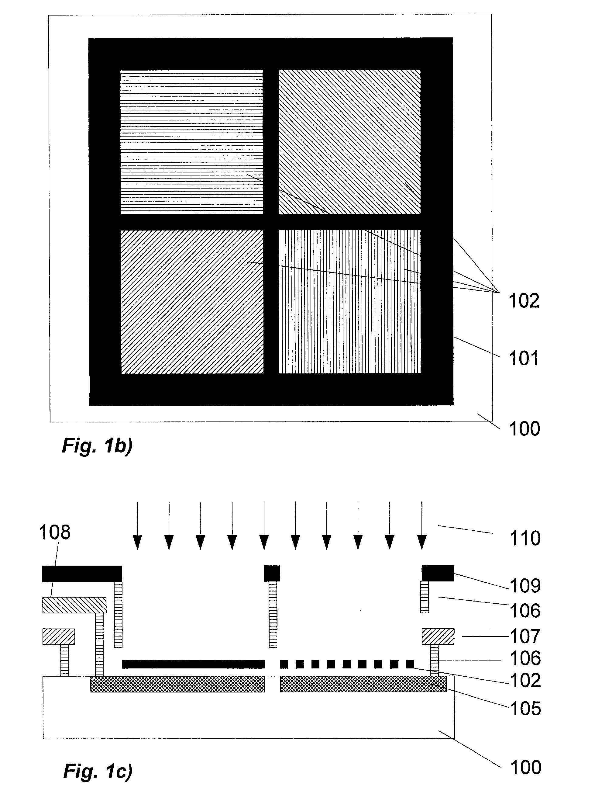
[0059]To make it possible to use a polarizing filter with short wavelengths light, that is in the visible range, implementation by other means than those discussed in example 1 is more economical. Because the large scale manufacture of polarization filters having appropriate properties is controlled, a combination of such sheets with lithographic methods may be employed to produce microstructured polarization filters. The most diverse manufacturing methods may be employed for the required polarization filters. Resin-imbedded nanotubes or nanowires also are applicable besides the conventional polymers. Such filters would be manufactured using comparable procedures with which large-area filters for instance are produced for LCD's. In other words, long-chain molecules, nanotubes or nanowires are oriented by an external force, ...

example 3

Polarization Sensors for Angle Measurement

[0065]A frequently encountered problem is measuring an angle at rotating parts, for instance to determine the position of a transducer (control stick, pedal etc.) or of a servo. As cited initially, commonplace measurement procedures incur restrictions for instance about resolution or adjustment tolerances as miniaturization increases and as the speed of measurement rises. Measuring angles by resorting to light's polarization may bypass many problems.

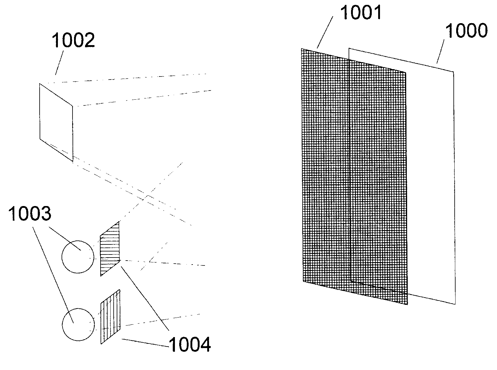
[0066]Conventionally a photosensor may be mounted for instance behind a rotatable polarization filter and be irradiated with polarized light of unknown polarization direction, and the signal measured at different angles of rotation and obeying Malus' law may be detected. When the signal is a maximum the orientation of the measuring polarization filter is identical with that of the incident light. Such a design is bulky and comparatively expensive. Also it presupposes that the signal being measure...


PUM


Abstract

The present invention relates to methods for manufacturing polarization sensitive respectively polarizing filters and to their application to polarizing photosensors used to measure the polarization of incident light, further to designs of polarization sensors measuring angles of rotation and strong electric or magnetic fields as well as to reproducing polarization equipment reproducing polarized signals or to reproduce independent signals.

Description

FIELD OF THE INVENTION[0001]The present invention relates to manufacturing methods of polarization-sensitive respectively polarizing filters, further to application of polarization-sensitive photosensors to measure the incident light polarization, embodiments of polarization sensors to measure angles of rotation and strong electrical or magnetic fields and further to polarization generating reproducing apparatus to reproduce polarized signals or to the reproduction of independent signals.BACKGROUND[0002]Polarization is an important property of light ordinarily not detected by the human eye. Whereas insects already for a long time find their way using the sky's scattered polarized light, humans have exploited polarization only lately. Sun glasses specifically suppress the sky's scattered light. Photographers place polarizing filters in front of the camera lens to suppress reflections from glass panes or other surfaces. Streak photography is significant in quality control, for instanc...

Claims


Application Information

Patent Timeline
Patent Type & Authority Patents(United States)
IPC IPC(8): G01J4/00G02B5/30G02B30/25
CPCG01J4/04H04N13/0438G02B5/3025H01L27/14625H04N13/341G01D5/344
Inventor GRAU, GUNTER
Owner GRAU GUNTER
Why Eureka
Try Eureka