
Injection control system

a piezoelectric fuel injector and control system technology, applied in the direction of electrical control, process and machine control, etc., can solve the problems of affecting the life span (durability) and adversely affecting the performance of the injector, and worse fuel economy, so as to reduce the length of time for which the actuator is exposed to high differential voltage and reduce the high differential voltage

Inactive Publication Date: 2011-11-08
DELPHI INT OPERATIONS LUXEMBOURG S A R L
View PDF14 Cites 12 Cited by
  • Summary
  • Abstract
  • Description
  • Claims
  • Application Information

AI Technical Summary

Benefits of technology

The invention provides methods for operating a piezoelectric actuator-controlled fuel injector in a way that reduces the high differential voltages to which the actuator is exposed and increases the operational life of the injector. The methods involve applying a discharge current to the actuator for a short period of time to initiate the injection event, and then maintaining the actuator at a specific temperature for a longer period of time. The methods also involve measuring or estimating certain engine parameters, such as fuel pressure and ton, and controlling the charging and discharging of the actuator based on these parameters. The invention can be used to operate multiple fuel injectors in an engine simultaneously, and the method may involve multiple fuel injection cycles.

Problems solved by technology

It has been recognised, however, that the existence of such a high voltage across the piezoelectric actuator for a relatively long portion of the operating cycle of the actuator may cause the degradation (“aging”) of the piezoelectric stack, leading to a change in its mechanical and / or electrical properties and, thus, adversely affecting the life span (durability) and performance of the injector.
These problems may be attributable, in part, to the higher stress levels exerted on the piezoelectric actuator at the higher differential voltage levels in a non-injecting state.
In any event, any resultant inaccuracies in fuel volume delivery will have a detrimental effect on combustion efficiency and lead to worse fuel economy and increased exhaust emissions.

Method used


Image

  • Injection control system
  • Injection control system
  • Injection control system

Examples


Embodiment Construction

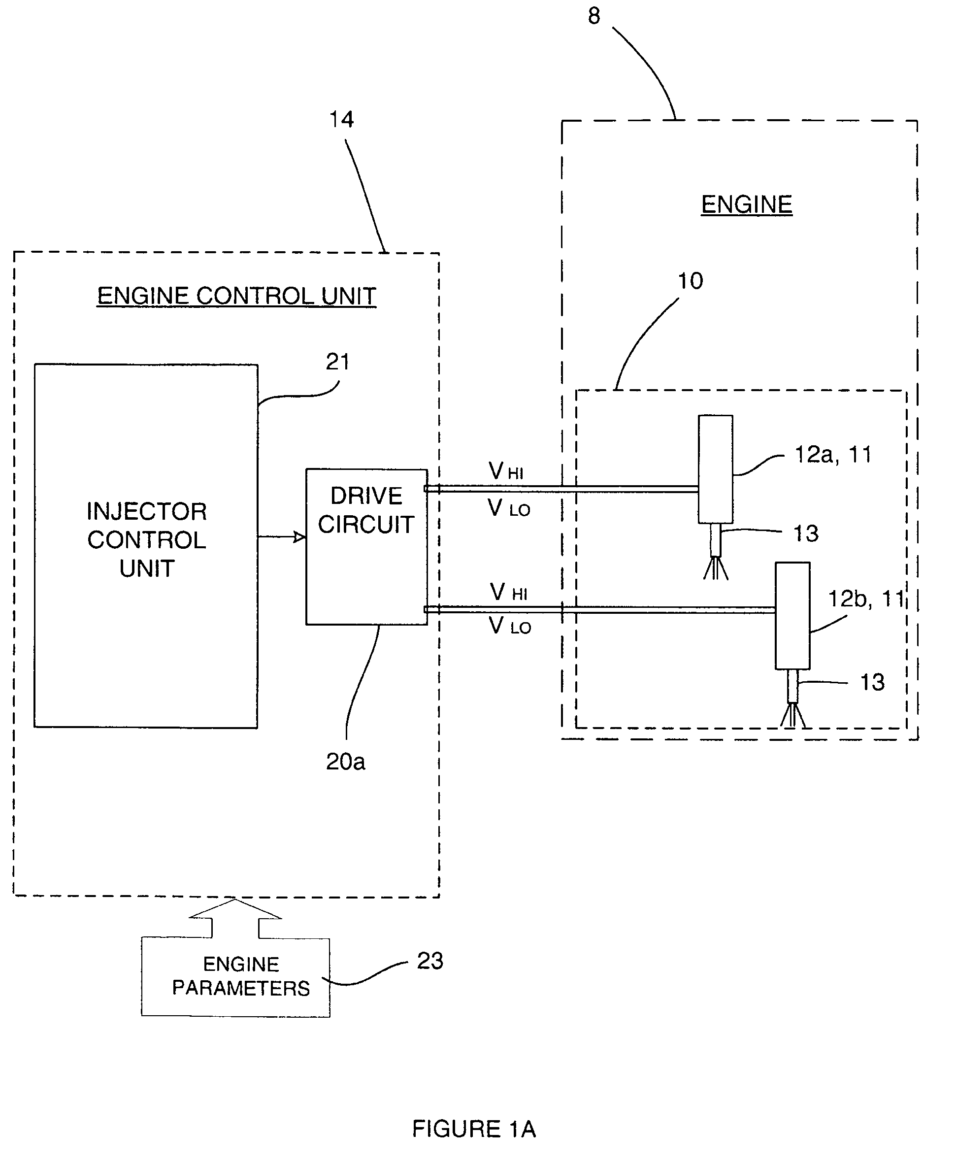
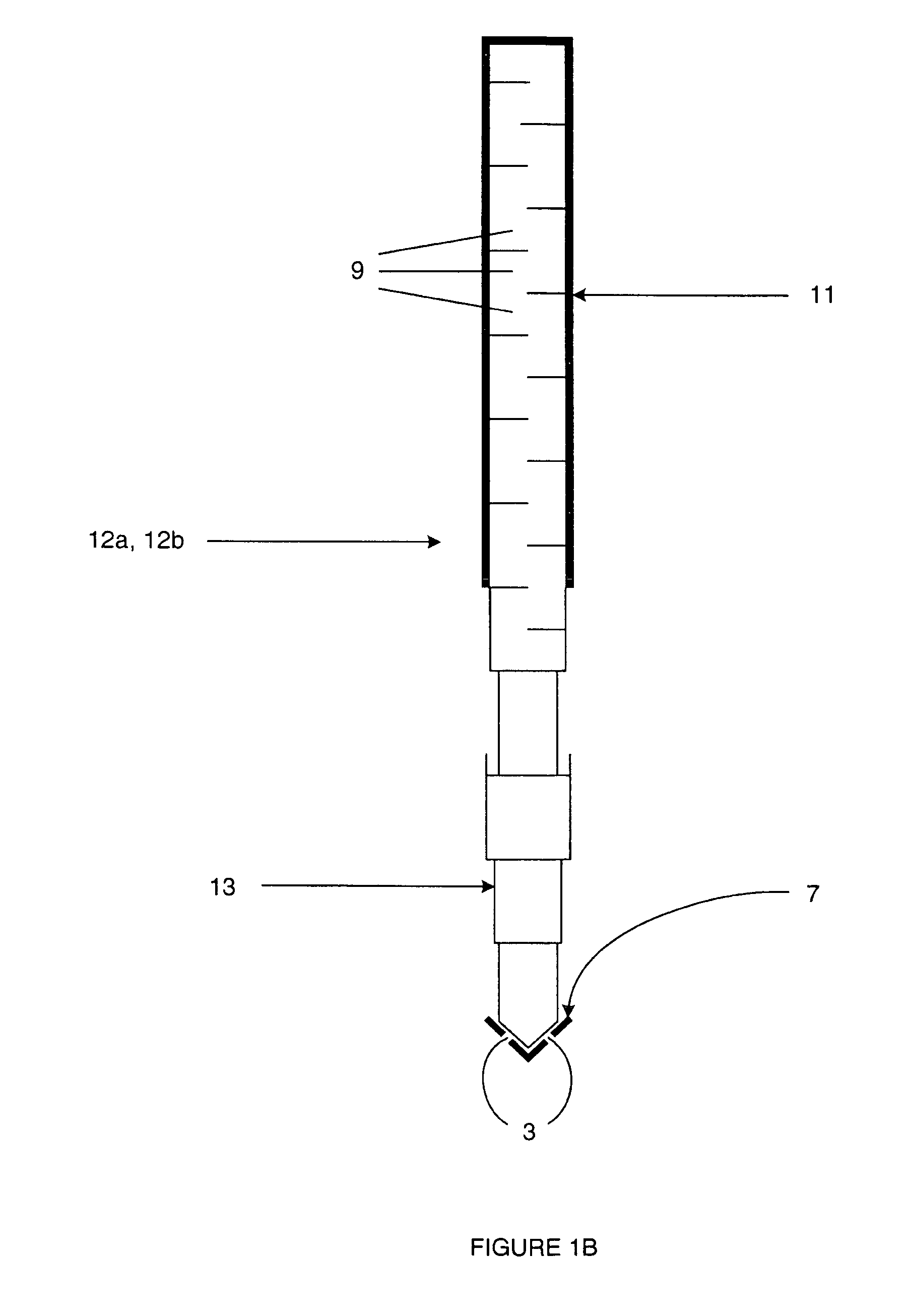
[0075]With reference to FIGS. 1A and 1B, an engine 8, such as an automotive vehicle engine, is generally shown having an injector arrangement comprising a first fuel injector 12a and a second fuel injector 12b. The fuel injectors 12a, 12b each have an injector valve needle 13 and a piezoelectric actuator 11 comprising a stack of piezoelectric elements 9. The piezoelectric actuator 11 is operable to control the position of an injector valve needle 13 relative to a valve needle seating 7. Depending on the voltage across the terminals of the piezoelectric actuator 11, the valve needle 13 is either caused to disengage the valve needle seating 7, in which case fuel is delivered into an associated combustion chamber / cylinder (not shown) of the engine 8 through a set of nozzle outlets 3; or is caused to engage the valve needle seating 7, in which case fuel delivery is prevented.

[0076]The fuel injectors 12a, 12b may, for example, be employed in a compression ignition internal combustion eng...


PUM


Abstract

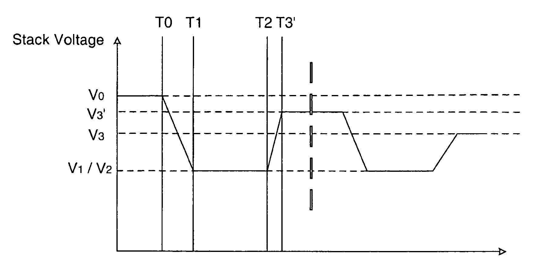
A method of operating a fuel injector including a piezoelectric actuator having a stack of piezoelectric elements, and wherein in use the injector communicates with a fuel rail, the method comprises: applying a discharge current to the actuator for a discharge period so as to discharge the stack from a first differential voltage level across the stack to a second differential voltage level across the stack; maintaining the second differential voltage level for a period of time; and applying a charge current to the actuator for a charge period so as to charge the stack from the second differential voltage level to a third differential voltage level; wherein the third differential voltage level is selected in dependence on at least two engine parameters, the at least two engine parameters selected from: rail pressure; the electric pulse time; and the piezoelectric stack temperature.

Description

FIELD OF THE INVENTION[0001]This invention relates to a method of operating a piezoelectric fuel injector. In particular, the invention relates to a method of operating a piezoelectric fuel injector so as to improve its operational life and to maintain fuel injection quantity accuracy.BACKGROUND OF THE INVENTION[0002]In an internal combustion engine, it is known to deliver fuel into the cylinders of the engine by means of a fuel injector. One type of fuel injector that permits precise metering of fuel delivery is a so-called ‘piezoelectric injector’. Typically, a piezoelectric injector includes a piezoelectric actuator that is operable to control movement, directly or indirectly, of a valve needle between injecting and non-injecting states. The valve needle is engageable with a valve needle seating to control fuel delivery through one or more outlet openings in the nozzle of the injector. A hydraulic amplifier may be situated between the actuator and the needle such that axial movem...

Claims


Application Information

Patent Timeline
Patent Type & Authority Patents(United States)
IPC IPC(8): F02M37/04F02M51/00H10N30/80
CPCF02D41/2096F02D2041/2051
Inventor SPADAFORA, PETER J.HOPLEY, DANIEL JEREMYTOLLIDAY, ADRIAN R.
Owner DELPHI INT OPERATIONS LUXEMBOURG S A R L
Learn More