Residential reverse osmosis system

a reverse osmosis and residential technology, applied in the field of systems and residential reverse osmosis, can solve the problem of limiting the bottom line manufacturing cost of these units

Active Publication Date: 2011-11-08
GE OSMONICS INC
View PDF33 Cites 7 Cited by
  • Summary
  • Abstract
  • Description
  • Claims
  • Application Information

AI Technical Summary

Problems solved by technology

Because these systems are only capable of producing a small rate of permeate, the storage tank is required on almost every system.
Moreover, there are several component co

Method used


Image

  • Residential reverse osmosis system
  • Residential reverse osmosis system
  • Residential reverse osmosis system

Examples


example membranes

[0097]Examples of RO membranes usable in a membrane element of the present system can be prepared by the following methods. One method for preparing a reverse osmosis membrane having improved flux properties includes treating a starting reverse osmosis membrane with dipropylammonium nitrate, diisopropylethylammonium nitrate, triethylammonium nitrate, tetraethylammonium nitrate, diethylammonium nitrate or tetraethylammonium borate, or a mixture thereof (and optionally drying) to provide a reverse osmosis membrane having improved flux properties. One method of improving the permeability of a reverse osmosis membrane includes treating a reverse osmosis membrane with an aqueous solution of an organic nitrate or borate salt, drying; and optionally recovering the membrane.

[0098]Reverse osmosis membranes which can be treated according to the methods described herein include the reaction product of polyacyl halides, polysulfonyl halides or polyisocyanates and polyamines or bisphenols. The r...

example 1

[0120]Sample membrane elements were formed having the following specifications and were tested with the results as shown:

[0121]

Flow, gpdSample#@77 F.% Rejection1227.0793.6%2234.6294.8%

Element Specifications

[0122]

#Leafs1Permeate Carrier H-.06valueFlat Sheet A-value23.9Flat Sheet Rejection (%)97Dimensions (in)Scroll Width18Diameter2.4Feed Spacer Thickness21(mils)Permeate Carrier13Thickness (mils)Leaf Length (ft)6.4Tube OD (in)1β (Efficiency %)74.5

Test Conditions (Element)

[0123]

Pressure (psig)65Pressure output (psig)41Feed Cond (uS)1082Feed Conc (ppm)534Feed T (deg F.)75.56

Test Conditions (Flat Sheet)

[0124]

Pressure (psig)100Feed Conc (ppm)500Feed T (deg F.)77

example 2

Theoretical optimized 2 element design @ 65 psi, 500 ppm NaCl / RO

25% recovery 360GPD / element

[0125]Element Specifications

[0126]

#Leafs1PC H-value.03Flat Sheet A-value30Flat Sheet Rejection (%)97Dimensions (in)Scroll Width18Diameter2.6FS Thickness (mils)21PC Thickness (mils)13Leaf Length (ft)6.9Tube OD (in)1β (Efficiency %)81.2

Test Conditions

[0127]

Pressure (psig)65Pressure output (psig)65Feed Conc (ppm)500Feed T (deg F.)77

Test Conditions (Flat Sheet)

[0128]

Pressure (psig)100Feed Conc (ppm)500Feed T (deg F.)77


PUM

PropertyMeasurementUnit
Massaaaaaaaaaa
Massaaaaaaaaaa
Massaaaaaaaaaa

Abstract

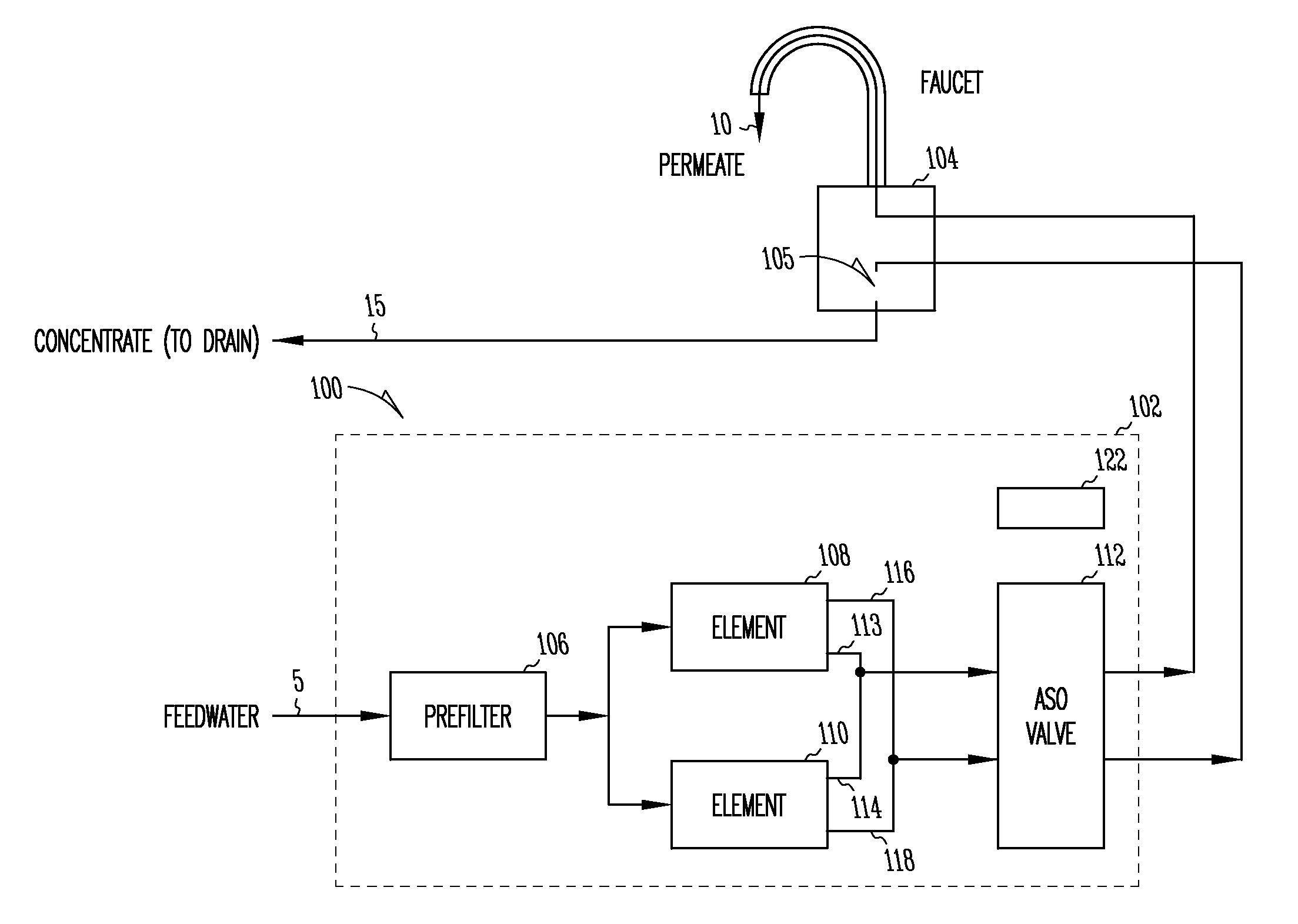
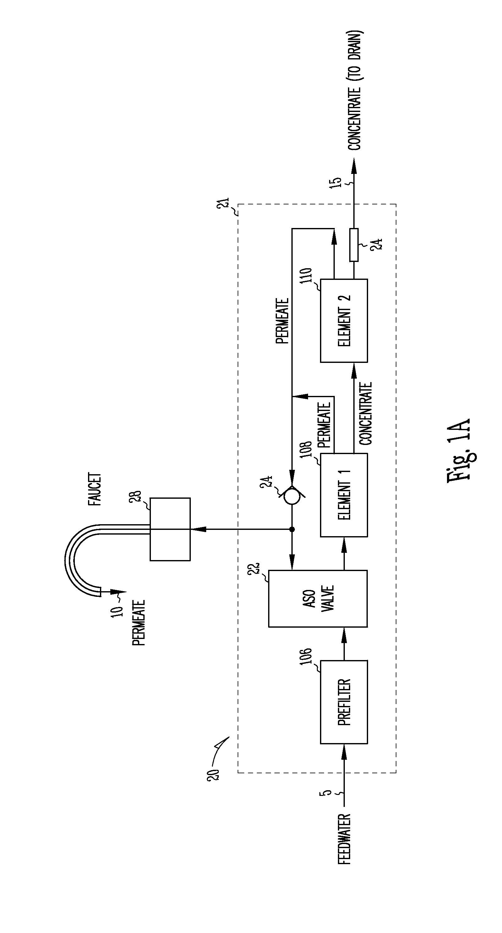
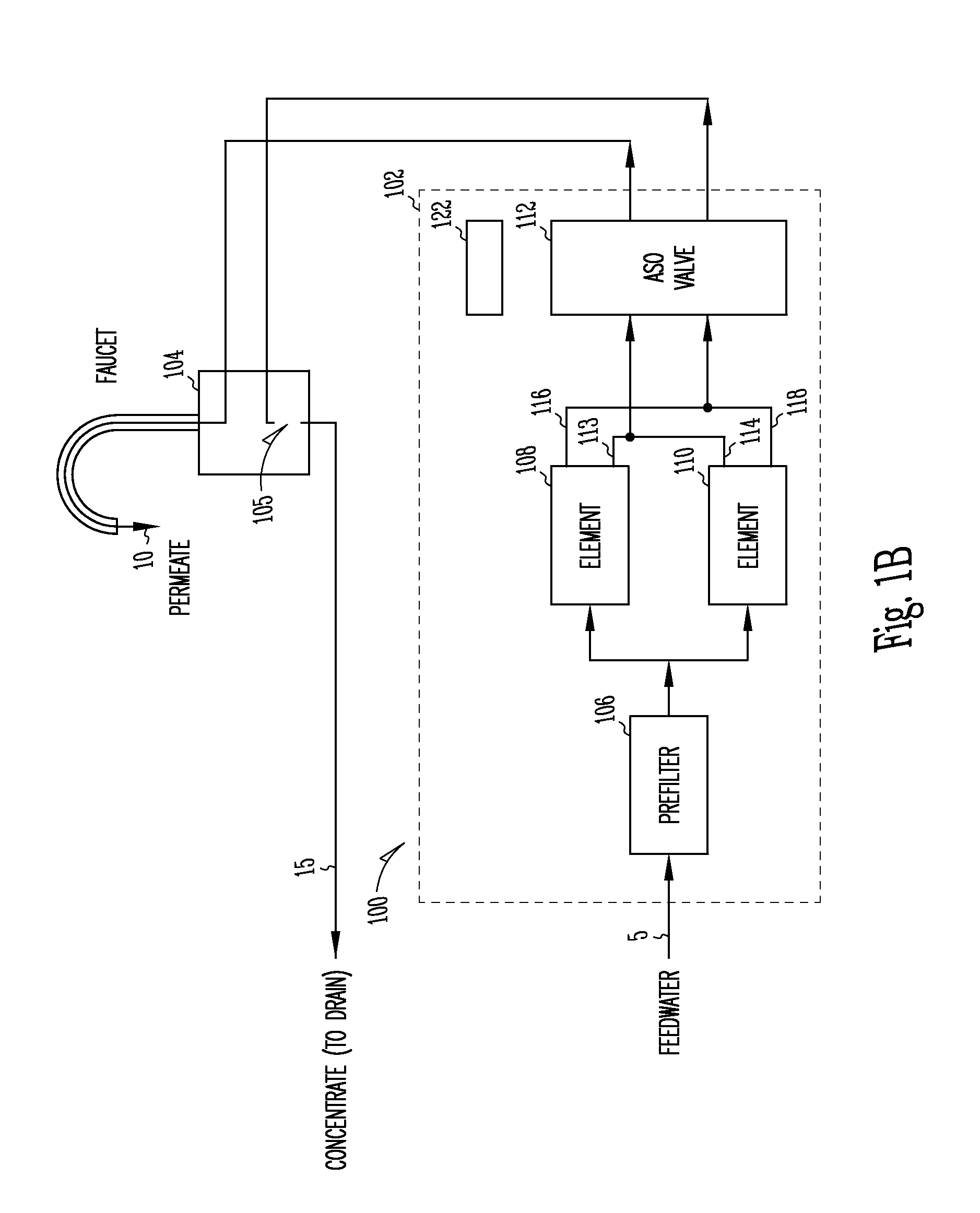
Some embodiments of the present invention relate to a reverse osmosis (RO) system that includes a housing and a pre-filter within the housing such that feed water flows into the housing and enters the pre-filter. The reverse osmosis (RO) system further includes a membrane element within the housing such that the pre-filtered water flows from the pre-filter and enters the membrane element and permeate exits the membrane element through the housing. In some embodiments, the housing includes a first end cap at one end and a second end cap at an opposing end such that feed water flows through the first end cap into the pre-filter and pre-filtered water flows from the pre-filter into the first end cap. In addition, the pre-filtered water may flow from the first end cap to the membrane element such that permeate exits the membrane element through the first end cap in order exit the housing.

Description

CROSS-REFERENCES TO RELATED APPLICATIONS[0001]This application is continuation of U.S. application Ser. No. 12 / 208,368, filed Sep. 11, 2008 now U.S. Pat. No. 7,862,710 , which is a division of U.S. application Ser. No. 10 / 524,155, filed on Jan. 30, 2006 and issued on Apr. 7, 2009, as U.S. Pat. No. 7,513,996, which is a U.S. National Stage Filing under 35 U.S.C. 371 from International Application Number PCT / US2003 / 025408, filed Aug. 12, 2003 and published in English as WO 2004 / 014528 Al on Feb. 19, 2004, which claims the benefit of U.S. Provisional Application, Serial Number 60 / 402,754, filed Aug. 12, 2002, under 35 USC 119(e), which applications and publication are incorporated herein by reference in their entirety. This application is related to PCT Application PCT / US 03 / 06587, filed Mar. 3, 2003 and to PCT Application PCT / US 03 / 17527, filed Jun. 4, 2003, both of which are incorporated herein by reference in their entirety.FIELD OF THE INVENTION[0002]This invention relates to the f...

Claims


Application Information

Patent Timeline
IPC IPC(8): B01D61/06B01D63/10B01D61/00B01D61/02B01D61/08B01D61/10B01D65/00C02F1/44
CPCB01D61/022B01D61/025B01D61/08B01D61/10B01D61/12B01D65/00C02F1/441B01D2313/02B01D2313/06B01D2313/18B01D2313/20B01D2313/90B01D2317/04C02F2307/06B01D61/026
Inventor KLOOS, STEVEN D.ROLCHIGO, PHILIP M.KURTH, CHRISTOPHER J.KUNG, CHIACARTWRIGHT, THOMAS J.RECKIN, RICHARD M.SIETH, KENNETH J.
Owner GE OSMONICS INC
Why Eureka
Try Eureka