Unlock instant, AI-driven research and patent intelligence for your innovation.

Methods of processing magnetotelluric signals

a magnetotelluric signal and processing method technology, applied in the field of magnetotelluric surveys, can solve the problems of the difficulty of detecting the inability to accurately identify the location of the magnetotelluric signal, etc., to achieve accurate indication. , the effect of reducing the time and expense involved in conducting the seismic survey

Inactive Publication Date: 2011-11-08
BYERLY KENT A
View PDF56 Cites 5 Cited by
  • Summary
  • Abstract
  • Description
  • Claims
  • Application Information

AI Technical Summary

Benefits of technology

"The invention provides methods for processing magnetotelluric data to identify subterranean deposits. The data comprises the amplitude of alternating magnetic or electrical fields recorded over time in at least two vector components at one or more locations in an area of interest. The methods filter the data at a set of predetermined frequencies to separate amplitude data at each frequency from the remainder of the data. The resistance values at each frequency are statistically analyzed to determine a value correlated to the resistance of the earth at each frequency. The methods also provide a method for collecting magnetotelluric signals and processing them through the novel data processing methods. The technical effects of the invention are better ability to remove unwanted noise, provide values correlating to subsurface resistivity at defined depths, and render a more accurate indication of the presence or absence of valuable deposits in the survey area."

Problems solved by technology

Test drilling, however, is extremely expensive and time consuming.
Thus, it is rarely a practical first option for exploring unknown and unproven areas.
Seismic surveys, however, only identify geological formations capable of holding hydrocarbon deposits.
Moreover, the time and expense involved in conducting a seismic survey, while considerably less than that of test drilling, is nevertheless substantial.
Despite the considerable theoretical and practical advantages of magnetotelluric surveying, however, its promise has not been fully realized, so much so that such surveys are often met with the skepticism normally reserved for water witching, divining and the like.
The applicability of such methods, however, is severely limited.
For example, they are extremely difficult to detect reliably during overcast periods and during rainstorms, and they are almost undetectable at night.
Thus, while the DC component may be analyzed to make inferences about the overall resistivity of the earth below a survey location, it is impossible to deduce the resistivity of the earth at specific depths, or to detect differences in resistivity at different depths.
Magnetotelluric signals, however, are extremely weak and typically are very noisy.
Prior art methods have not provided effective methods for improving the quality of magnetotelluric signals, i.e., their signal to noise ratio.
At the same time, however, the accuracy of the overall survey depends on an unstated, though faulty assumption that the received signals are relatively constant, since data are being collected and analyzed from various locations in the survey at different times. Moreover, by relying on “snap shots” of fluctuating signals, the results of such methods are difficult to replicate from survey to survey.
Thus, to date there has been little success in systematically analyzing magnetotelluric signals despite the availability of quiet detection and recording equipment and efficient and powerful digital computers.
It is believed, therefore, that the lack of success in large part derives from the inability of the prior art to recognize the essentially chaotic nature of magnetotelluric signals and to construct effective models for isolating and identifying meaningful data in magnetotelluric signals.
While the methods disclosed in Byerly '747 represent a significant advance over other prior art methods, conventional methods of processing magnetotelluric data have yet to gain substantial commercial acceptance or widespread use.

Method used


Image

  • Methods of processing magnetotelluric signals
  • Methods of processing magnetotelluric signals
  • Methods of processing magnetotelluric signals

Examples


example

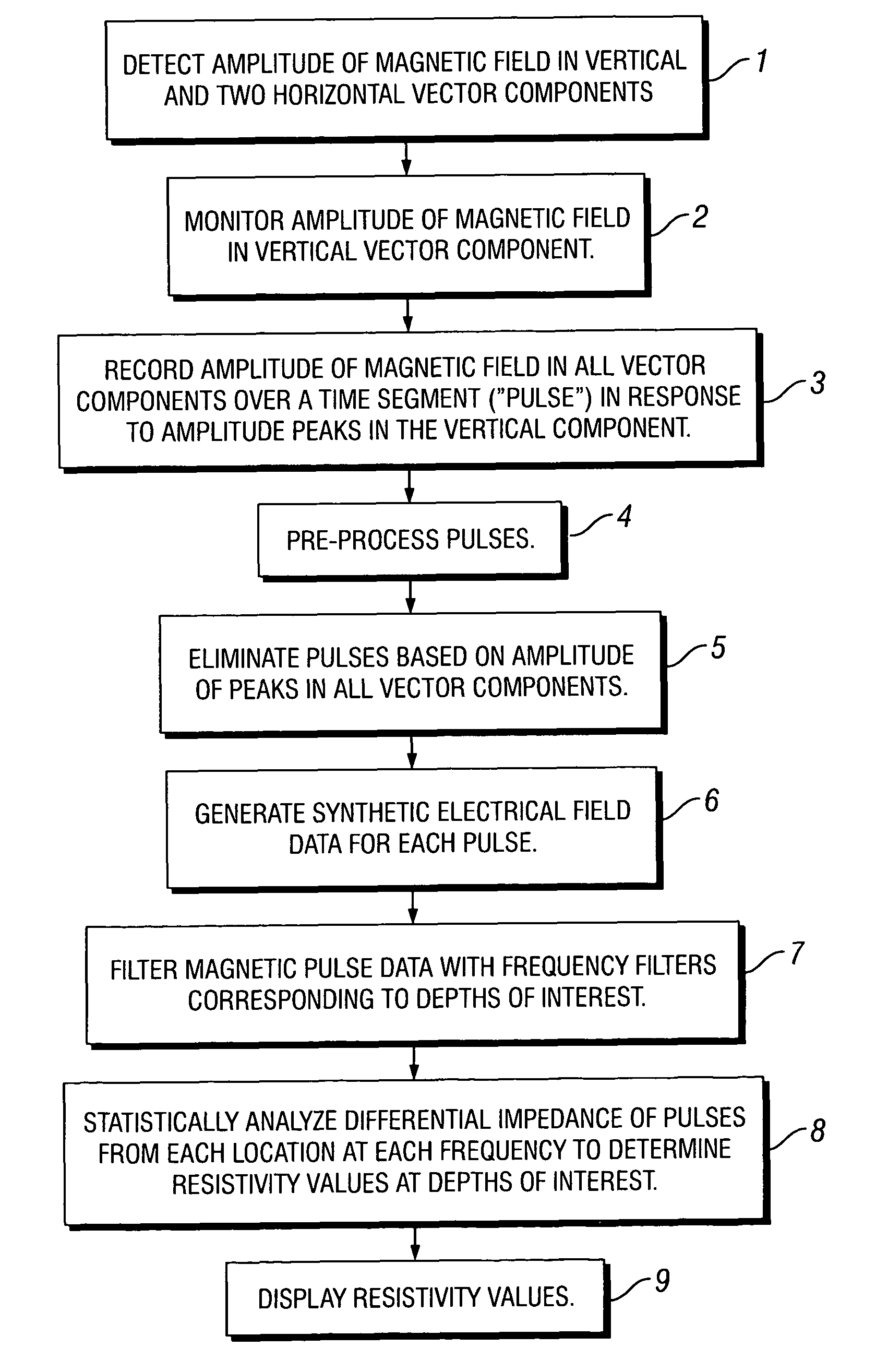
[0108]A magnetotelluric survey was conducted in a known oil and gas producing field near Madisonville, Tex. Magnetic data were collected at a single location using a three-channel antenna oriented orthogonally in vertical, north-south, and east-west vectors. The data were recorded and digitally stored using a high gain audio amplifier and a laptop computer utilizing a DSP acquisition system, all of which are commercially available and typical of the equipment that may be used in gathering and processing magnetotelluric data. The data were sampled at a rate of 30,702 Hz. Approximately 500 pulses were recorded in response to thresholds triggered on the vertical channel. The thresholds were set at 6 sigma from the mean absolute value of the amplitude level, and the pulses were recorded as 4,096 24-bit samples. The range of depth investigated was from 6,000 to 12,000 feet at a resolution of 20 feet.

[0109]Each pulse was filtered to remove 60 Hz and harmonics and frequencies outside the r...


PUM


Abstract

A method for processing magnetotelluric data to identify subterranean deposits is provided for. The data comprise the amplitude of alternating magnetic or electrical fields recorded over time in at least two vector components at one or more locations in an area of interest. Amplitude pulses are identified in the data, wherein the pulses are time segments comprising an amplitude peak meeting defined threshold criteria in at least one vector component. The pulses are filtered at a set of predetermined frequencies to separate amplitude data at each frequency from the remainder of the amplitude data in the pulses. The frequencies correspond to subterranean depths over a range of interest. Differential impedances ΔZ of the pulses at each frequency at each location are then statistically analyzed to determine a value correlated to the resistance of the earth at each frequency. The resistance values are indicative of the presence or absence of deposits at the corresponding subterranean depth at the location.

Description

BACKGROUND OF THE INVENTION[0001]The present invention relates to magnetotelluric surveys and, more particularly, to improved methods for processing magnetotelluric signals.[0002]There are many different methods for locating hydrocarbon deposits and other natural resources in the earth's crust. Drilling test holes in an area of interest is the most direct method. Samples from various depths may be obtained and analyzed for evidence of commercially exploitable deposits. Test drilling, however, is extremely expensive and time consuming. Thus, it is rarely a practical first option for exploring unknown and unproven areas.[0003]Seismic surveys are one of the most important techniques for discovering the presence of hydrocarbon deposits. A seismic survey is conducted by deploying an array of energy sources, such as dynamite charges, and an array of sensors in an area of interest. The sources are discharged in a predetermined sequence, sending seismic energy waves into the earth. The refl...

Claims


Application Information

Patent Timeline
Patent Type & Authority Patents(United States)
IPC IPC(8): G01V3/00G01V5/00
CPCG01V3/082
Inventor BYERLY, KENT A.
Owner BYERLY KENT A
Features
  • R&D
  • Intellectual Property
  • Life Sciences
  • Materials
  • Tech Scout
  • Unparalleled Data Quality
  • Higher Quality Content
  • 60% Fewer Hallucinations
Learn More