Method and apparatus for disinfecting a refrigerated water cooler reservoir

a technology of refrigerated water cooler and reservoir, which is applied in the direction of domestic cooling apparatus, multi-stage water/sewage treatment, defrosting, etc., can solve the problems of difficult to convince everyone who handles these bottles to wash their hands frequently enough, difficult to clean the reservoir in such a water dispenser, and time-consuming project for cleaning the reservoir, etc., to achieve the effect of improving the response rate, reducing the air density and increasing the flow ra

Inactive Publication Date: 2011-11-15
S I P TECH L L C
View PDF51 Cites 17 Cited by
  • Summary
  • Abstract
  • Description
  • Claims
  • Application Information

AI Technical Summary

Benefits of technology

[0033]A reservoir contained within the cabinet holds water to be cooled and dispensed. A refrigeration system cools the water within the reservoir. The reservoir can optionally be heated. A diffuser (e.g. ring) emits bubbles into the reservoir, the diffuser being disposed within the reservoir at the lower end portion thereof and preferably next to the reservoir wall so that bubbles emitted by the diffuser help scrub the reservoir wall.
[0080]Heat from the ozonated air is transferred to the thin bimetal walled, heli-coiled bellows valve body, promoting linear expansion of same, thus allowing a slightly greater airflow to diffuser until air temperature is again in an optimal range. In this case the auto-valving flow control mechanism resembles the conventional water cooled engine's thermostat with addition of a flow adjustment. Since air is a poor conductor of heat, airflow is made to spiral around the entire helical surface of the bimetal bellows to ensure a maximum, even heat transfer to the metal. The second adjustable orifice or thermostat orifice and seat is located at the base of the valve / bellows. Once first orifice is adjusted for airflow during cold operation, the mechanism is free to respond to changes in temperature for secondarily regulating airflow and air temperature automatically. Device is simple, consists of minimum quantities of readily available inexpensive materials and can be fabricated and sold inexpensively. Device is claimed for use with water dispenser ozone sanitization equipment as an auto-airflow / temperature control optimizer.

Problems solved by technology

One of the problems with cabinet style water dispensers is that of cleansing the reservoir from time to time.
The reservoirs are typically contained within the confines of the cabinet and are not easily accessed and cleaned by consumers or end users.
For inverted bottle type dispensers, in addition to the problem of an open top, the five gallon bottles are themselves a source of bacteria and germs.
Unfortunately, it is difficult to convince every person that handles these bottles to wash their hands frequently enough.
The cleansing of the reservoir in such a water dispenser is a time consuming project that is typically not performed at regular intervals.
The dispensing spigots that are provided on common cabinet type water dispensers can also be a source of contamination.
These spigots are typically manually operated and are therefore a source of contamination from the users that operate them.
Process ozone diffusion by bubble reactor method in small static volumes of water with abbreviated water columns to diffused ozone levels satisfactory to disinfect microorganisms in brief time periods can be difficult to achieve.
During the process of re-engineering equipment and reducing costs to fit small application needs, it was found that beyond basic principles, much of the available industrial technology proved of limited value.
Attempts at using prior art to address small applications have resulted in either failure to achieve minimal levels of sanitization or where success was achieved, systems that could not remain cost competitive.
Due to cost and space constraints small applications are limited to the use of small ambient air fed ozonators capable of generating less than 1% by weight ozone.
A large hurdle for small applications exhibiting static water volumes with a short (i.e., a few inches) water column is the ozone to water contact time.
An additional difficulty is the loss of minimal head pressure, production of a large bubble with inadequate surface contact area resulting in a near total systems loss of process ozone.
Though large applications address flow control through fine bubble diffusers, its use is confined to high ozone concentration feed gas, fed through a high volume of fine bubble diffusers primarily for oxidation of bio-solids in moving volumes of water where bubble retention time is not critical.
However, the lack of need generated by past engineering success has caused industry to stop short of original goals.
Higher pressure materials are not optimal for small low pressure / volume open systems applications as they decrease pump life and often do not supply an adequate volume of small bubbles for ozonation.
Otherwise, bubble size will increase to non-optimal proportions.
Industry experience has been negatively influenced by misapplication of fine pore size diffusers to high solids and TDS fluids that promote rapid pore plugging, experience that crossed over to low mineral and solids water species like potable water disinfection.
Furthermore, large commercial and industrial applications could not afford downtime on dynamic systems that operate 24 hours a day.
The use of very fine pore size diffusers application was largely abandoned by wastewater and potable water treatment out of past reservations and lack of research data for generating optimally engineered materials.
To date, the recent interest in small applications has not triggered mainstream development of new diffuser materials / geometry innovations.
This is often complicated by an inability to effectively seal off material connection air leaks.

Method used


Image

  • Method and apparatus for disinfecting a refrigerated water cooler reservoir
  • Method and apparatus for disinfecting a refrigerated water cooler reservoir
  • Method and apparatus for disinfecting a refrigerated water cooler reservoir

Examples


Embodiment Construction

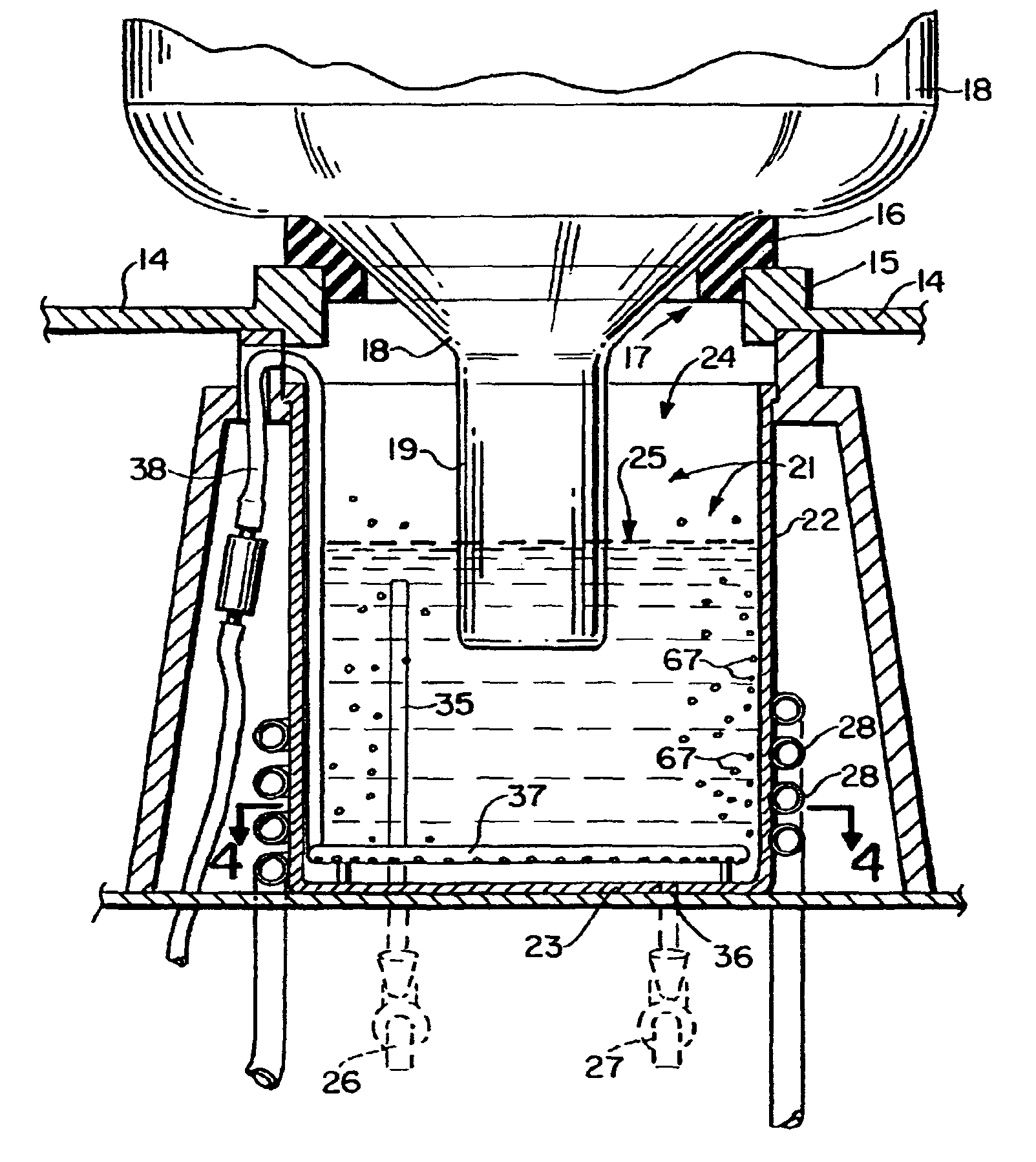
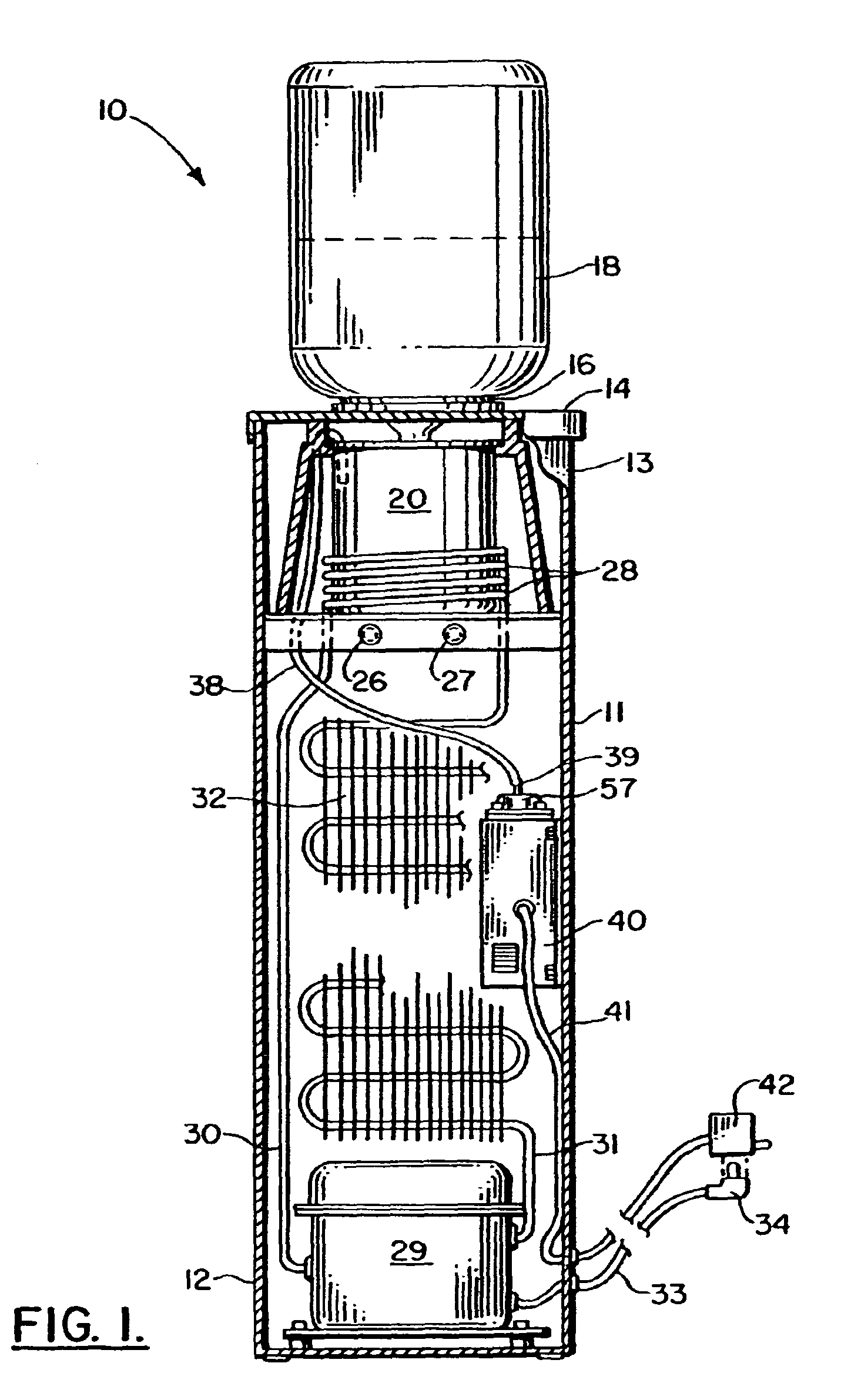
[0145]FIGS. 1-3 show generally the preferred embodiment of the apparatus of the present invention designated by the numeral 10 in FIG. 1. Water dispenser 10 provides an improved apparatus that sanitizes the open reservoir from time to time with ozone. The apparatus 10 includes a cabinet 11 having a lower end portion 12 and an upper end portion 13. The upper end portion 13 carries a cover 14 having an opening 17.

[0146]The opening 17 provides an annular flange 15 and a gasket 16 that defines an interface with bottle 18. The bottle 18 is a commercially available bottle that is typically of a several gallon volume (e.g. five gallons) in the United States. The bottle 18 provides a constricted bottled neck 19 that is placed inside an open reservoir 20 as shown in FIGS. 1 and 3 during use. The bottle neck 19 has an opening for communicating with a reservoir 20 at the interior of the cabinet 11 that holds the water product to be dispensed and consumed. When the reservoir 20 is lowered durin...


PUM

PropertyMeasurementUnit
distanceaaaaaaaaaa
distanceaaaaaaaaaa
sizesaaaaaaaaaa

Abstract

A method and apparatus for providing sanitized water in a cabinet and spigot type bottled water dispenser features an ozone generating system to generate ozone for sanitizing the water. Ozone is generated and collected within an ozone generator housing. A blower transmits air to the ozone generator housing. The air carries the ozone that is generated through a flow line to an air diffuser that is positioned upstream of the spigot (or spigots) used to dispense water. In one embodiment, a valve that is activated on the spigot to dispense water also activates the blower and ozone generator. In other embodiments, a flow sensor activates the ozone generator and blower. Various spigot and flow sensor arrangements are disclosed as a part of the overall apparatus and method.

Description

CROSS-REFERENCE TO RELATED APPLICATIONS[0001]This is a continuation application of U.S. patent application Ser. No. 10 / 463,870, filed Jun. 17, 2003 (now U.S. Pat. No. 7,640,766), which claimed priority to U.S. Provisional patent application No. 60 / 389,439, filed 17 Jun. 2002, is a continuation-in-part of U.S. patent application Ser. No. 10 / 173,133, filed 17 Jun. 2002, and of International Patent Application No. PCT / US02 / 19158, also filed 17 Jun. 2002. Priority of each of these applications is hereby claimed and incorporated herein by reference.[0002]Hereby incorporated herein by reference are U.S. patent application Ser. No. 09 / 996,328, filed 28 Nov. 2001; U.S. patent application Ser. No. 09 / 881,796 filed 15 Jun. 2001; U.S. patent application Ser. No. 09 / 954,849, filed 18 Sep. 2001; U.S. patent application Ser. No. 09 / 472,320, filed 23 Dec. 1999; and U.S. patent application Ser. No. 09 / 220,554, filed 23 Dec. 1998.STATEMENT REGARDING FEDERALLY SPONSORED RESEARCH OR DEVELOPMENT[0003]N...

Claims


Application Information

Patent Timeline
Patent Type & Authority Patents(United States)
IPC IPC(8): F25D3/00B67D7/76A61L2/20B67D1/00B67D3/00C02F1/78
CPCA61L2/202B67D3/0029C02F1/78B67D2210/00013B67D2210/00023C02F2201/782C02F2209/40C02F1/685C02F2209/005C02F9/20
Inventor SHELTON, JAMES J.
Owner S I P TECH L L C
Why Eureka
Try Eureka