Cooling device for semiconductor element module and magnetic part

a cooling device and semiconductor element technology, applied in semiconductor/solid-state device details, electrical apparatus casings/cabinets/drawers, instruments, etc., can solve the problem of difficult to obtain high heat transfer efficiency for the entire cooling water passage, and achieve optimal heat dissipation from the entire magnetic part

Active Publication Date: 2011-11-22
HONDA MOTOR CO LTD
View PDF43 Cites 40 Cited by
  • Summary
  • Abstract
  • Description
  • Claims
  • Application Information

AI Technical Summary

Benefits of technology

[0007]The present invention is made in view of such background, and an object of the invention is to provide a cooling device for a semiconductor element module and a magnetic part, which is designed to have improved cooling efficiency of a heat sink with cooling fins.

Problems solved by technology

Thus, the cooling device formed by integrally connecting the cooling fins extending along the circulation direction of the cooling water passage across the entire length of the cooling water passage as disclosed in the Japanese Patent Application Laid-open No. 2004-349324 has a thermal entrance region only at the inlet of the cooling water passage, thus it is difficult to obtain high heat transfer efficiency for the entire cooling water passage.

Method used


Image

  • Cooling device for semiconductor element module and magnetic part
  • Cooling device for semiconductor element module and magnetic part
  • Cooling device for semiconductor element module and magnetic part

Examples


embodiment 1

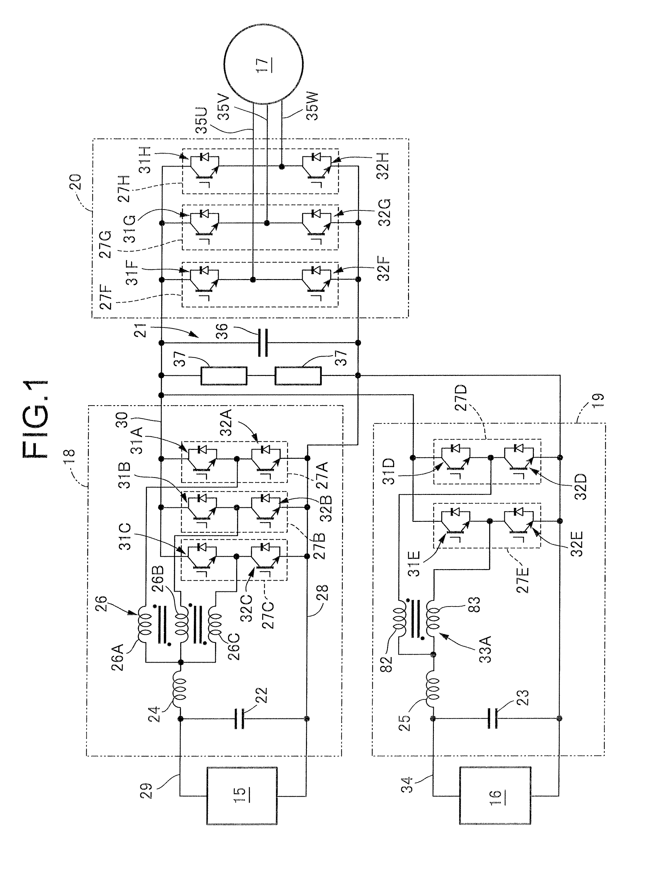
[0078]In the following, Embodiment 1 of the present invention is described referring to FIGS. 1 to 24. At first, referring to FIG. 1, a power conversion device is a device to be installed in a vehicle to convert direct current power obtained from a fuel cell 15, which is a first direct current power supply, and direct current power obtained from a storage battery 16, which is a second direct current power supply, into three-phase alternating current power to be supplied to an electric motor 17 generating power to drive a driving wheel. The power conversion device includes a first converter 18 which steps up or down the direct current voltage obtained from the fuel cell 15, a second converter 19 which steps up or down the direct current voltage obtained from the storage battery 16, an inverter 20 which converts the direct current voltage from the first and second converters 18 and 19 into an alternating voltage to drive the electric motor 17, and a DC link capacitor unit 21 provided ...

embodiment 2

[0156 of the present invention is described referring to FIGS. 25 to 29. The components of Embodiment 2 corresponding to those of Embodiment 1 are shown in the drawings with the same reference numerals as used in Embodiment 1, and their detailed descriptions are omitted.

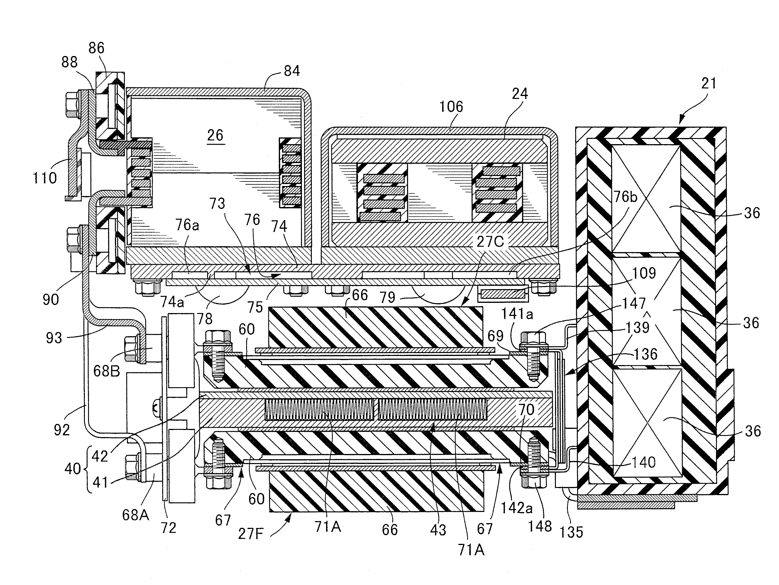
[0157]As shown in FIGS. 25 and 26, the six chips 47, 48, 49, 50, 51, 52 included in each of the first to eighth positive side switching elements 31A to 31H and the first to eighth negative side switching elements 32A to 32H are arranged by twos side-by-side along the circulation direction 46 of the cooling water in the first cooling water passage 43, i.e., the chips 47, 48, the chips 49, 50, and the chips 51, 52 are arranged in such manner that each pair is arranged side-by-side along the circulation direction 46.

[0158]The first cooling water passage 43 included in the first heat sink 40 has multiple cooling fins 71B which are integrally molded of a light metal such as aluminum alloy, having a continuous U or V shape...

embodiment 3

[0166 of the present invention is described with reference to FIG. 30. The components of Embodiment 3 corresponding to those of Embodiments 1 and 2 are shown in the drawings with the same reference numerals as used in Embodiments 1 and 2, and their detailed descriptions are omitted.

[0167]The second inductor 25 and the two-phase transformer 33A are housed in a common second housing case 85B made of metal, which is mounted on the flat mounting surface 74b of the second heat sink 73.

[0168]The second housing case 85B includes a supporting plate portion 154B in contact with the cores 151, 152 of the second inductor 25 and the two-phase transformer 33A; and the cover portion 155 which is disposed contiguously to the supporting plate portion 154B and covers the second inductor 25 and the two-phase transformer 33A. The supporting plate portion 154B is formed to have a greater plate thickness than that of the cover portion 155, and multiple stud bolts 158 implanted in the supporting plate po...


PUM


Abstract

A cooling device for a semiconductor element module and a magnetic part, includes: a water-cooled type heat sink having a cooling water passage; a semiconductor element module including a plurality of chips arranged side by side in a circulation direction in the cooling water passage, the semiconductor element module being mounted on the heat sink; and a magnetic part including a core and a winding portion mounted on the core, the magnetic part being mounted on the heat sink or another heat sink. In the cooling device, a plurality of cooling fins is disposed to extend along the circulation direction in the cooling water passage in a manner that the plurality of cooling fins are separated into groups for the respective chips arranged side by side in the circulation direction, and that the groups of the cooling fins are offset from each other in a direction perpendicular to the circulation direction. Accordingly, it is possible to have improved cooling efficiency of a heat sink with cooling fins.

Description

CROSS-REFERENCE TO RELATED APPLICATIONS[0001]The present application claims priority under 35 USC 119 to Japanese Patent Application No. 2009-153789, filed on Jun. 29, 2009, Japanese Patent Application No. 2009-156665, filed on Jul. 1, 2009, and Japanese Patent Application No. 2009-161611, filed on Jul. 8, 2009 the entire contents of which are hereby incorporated by reference.BACKGROUND OF THE INVENTION[0002]1. Field of the Invention[0003]The present invention relates to a cooling device for a semiconductor element module and a magnetic part, comprising: a water-cooled type heat sink having a cooling water passage; a semiconductor element module including a plurality of chips arranged side by side in a circulation direction in the cooling water passage, the semiconductor element module being mounted on the heat sink; and a magnetic part including a core and a winding portion mounted on the core, the magnetic part being mounted on the heat sink or another heat sink.[0004]2. Descripti...

Claims


Application Information

Patent Timeline
Patent Type & Authority Patents(United States)
IPC IPC(8): H05K7/20
CPCH05K7/20927Y10T307/50H01L2224/32225
Inventor HIGASHIDANI, YOSHIHIKOKATO, TAKESHINAGANO, MASAOYOSHINO, TSUTOMU
Owner HONDA MOTOR CO LTD
Why Eureka
Try Eureka