High volume low speed fan

a high-volume, low-speed technology, applied in the direction of rotors, vessel construction, marine propulsion, etc., can solve the problems of inability to efficiently produce upward airflow, inherently limited contour variation of extruded fan blades, and require considerable and expensive post-processing, so as to achieve the effect of increasing airflow efficiency

Active Publication Date: 2011-11-29
AIRMOTION SCI
View PDF26 Cites 61 Cited by
  • Summary
  • Abstract
  • Description
  • Claims
  • Application Information

AI Technical Summary

Benefits of technology

[0019]The HVLS fan described herein provides improved air circulation and thermal control in a building by incorporating fan blades of a more versatile shape, and by providing the ability to vary the blade angles as well as rotational speed. The blades are molded of a composite or polymer material over a metal tube core for strength and ease of attachment to the fan hub, and are made in a symmetrical airfoil shape for efficient bidirectional airflow. The fan includes an intelligent control system allowing startup with approximately zero blade pitch angle for more economical power consumption and less motor wear. The control unit also allows both manual and automated control over blade pitch angle and rotational speed, and the overall fan structure and mounting system allows the unit to be installed at a height inside a variety of buildings where efficiency and degree of desired air movement can be maximized. This adjustability and the conical airflow profile resulting from the blade shape produce more efficient air destratification and air mixing. Multiple HVLS fans with alternating or mixed directions of airflow can further increase efficiency of air movement. The types of buildings where an HVLS fan is suitable for use include factories, warehouses, distribution centers, storage facilities, airplane-hangars and repair buildings, auto maintenance, storage and dealerships, hotel lobbies, retail stores, malls, churches, sports facilities and gymnasiums, dairy barns, animal feed and food storage facilities, food processing centers, poultry barns, livestock facilities, horse stables and riding arenas, barns, military facilities, or any other large building or space within a building where people or animals may benefit from improved air circulation.

Problems solved by technology

Extruded fan blades are inherently limited in contour variation along their length by the nature of the manufacturing process and may require considerable and expensive post-processing to have any contour variation.
These fan blades are also highly optimized for a single direction of airflow and would not be capable of efficiently producing an upwards airflow, which is very limiting.
The blades are also optimized for a particular limited range of mounting angles and for a columnar or cylindrical airflow profile, further limiting the utility of the inventions disclosed therein.
In addition, the uses taught by the '821, '016, '835 and '108 patents do not include de-stacking of air thermal layers or general temperature control.
This mounting style and the teaching of an airspeed constrained to 3-5 mph even further limit the utility of these inventions.
When a fan starts up, there is a spike in energy use partially caused by air resistance against the blades.
The steeper the blade angle, the greater the air resistance and resulting instantaneous energy demand.
This spike also can cause long-term damage to the motor itself as well as to the control and drive circuitry.
The columnar or cylindrical airflow taught by the '821, '016, '835 and '108 patents also limits the utility of the HVLS fans.
Additionally, mounting HVLS fans to ceilings or roofs is not always desirable, as having the fans spaced more distantly from the ceiling or roof and closer to the middle of the building may allow far better airflow and efficiency of use.

Method used


Image

  • High volume low speed fan
  • High volume low speed fan
  • High volume low speed fan

Examples


embodiment

Preferred Embodiment

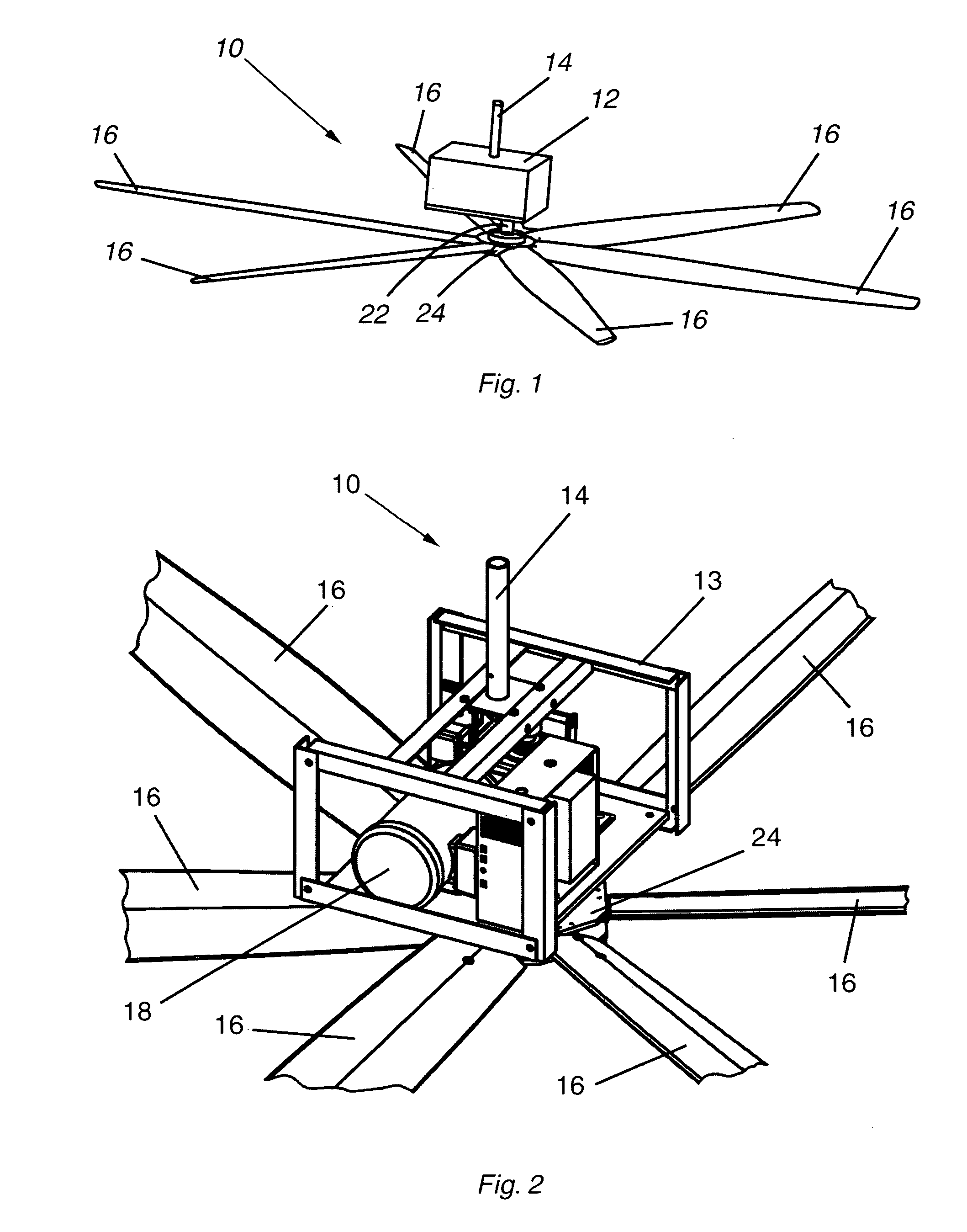
[0046]FIG. 1 shows the HVLS fan in an embodiment with 6 blades. The fan drive motor is preferably powered by a type of motor drive circuit known as a variable frequency drive, (VFD) preferably mounted with the fan and controlled by a control unit having a portion that is accessible to the user. Note that the VFD is not shown in the Figures and that while the user-accessible portion of the control unit is located at a distance from the fan itself, other portions of the control unit including some sensors and circuitry are located with the fan. The VFD and the line voltage portion of the power electronics are located up in the fan enclosure, which simplifies installation as to wiring, and also provides a safer set-up since only low voltage wiring connections or alternatively remote or networked connections, without the need for costly power wiring and conduit, are necessary to connect to the user-accessible portion of the control unit. The fan 10 is shown with the ...


PUM


Abstract

A high volume low speed (HVLS) fan provides improved air circulation and thermal control in a building by incorporating composite fan blades pivotable to both positive and negative pitch angles. The blades are molded of polymer material over a metal tube core for strength and ease of attachment to the fan hub, and have a symmetrical airfoil shape to produce an efficient bi-directional conical airflow. The fan includes a control unit providing manual and automated intelligent control over blade angle and rotational speed, as well as startup with approximately zero blade angle for more economical power consumption and less motor wear. The fan structure and mounting system allows the fan to be installed at an optimal height inside a variety of buildings to provide increased efficiency of air destratification and air mixing. An array of multiple HVLS fans with alternating directions of airflow can further increase efficiency of air movement.

Description

CROSS REFERENCE TO RELATED APPLICATIONS[0001]I claim the benefit of the priority date of Provisional Patent Application No. 61 / 002,488 filed Nov. 9, 2007 entitled HIGH VOLUME LOW SPEED FAN.STATEMENT REGARDING FEDERALLY SPONSORED RESEARCH OR DEVELOPMENT[0002]N / ABACKGROUND OF THE INVENTION[0003]1. Field of the Invention[0004]The present invention relates generally to rotary fans with elongated blades configured to move large volumes of air at low rotational speeds. This type of fan is usually configured to be mounted with the blades in a horizontal plane and above the area where most of the air moving is to occur, and is generally referred to as a high volume low speed (HVLS) fan.[0005]2. Description of the Prior Art[0006]A high volume low speed fan will generally have at least 6 blades, in the majority of cases each blade being at least 4 feet in length. A primary use for HVLS fans is to move air for ventilation, temperature control and cooling of people and livestock in large, relat...

Claims


Application Information

Patent Timeline
Patent Type & Authority Patents(United States)
IPC IPC(8): F04D29/18F03B7/00B64C11/00B64C27/00B63H3/00F04D29/26
CPCF04D25/088F04D27/004F04D29/362F05D2260/85Y02B30/70
Inventor MADSEN, JOE E
Owner AIRMOTION SCI
Why Eureka
Try Eureka