Wind turbine and method for determining at least one rotation parameter of a wind turbine rotor

a wind turbine and rotation parameter technology, applied in the direction of wind motors with perpendicular air flow, testing/calibration of speed/acceleration/shock measurement devices, wind energy generation, etc., can solve the problem of introducing artificial control requirements, measuring errors, and apparent cyclic oscillation of the measured rotor speed. achieve the effect of improving the measurement of at least one rotation parameter

Active Publication Date: 2012-01-10
SIEMENS GAMESA RENEWABLE ENERGY AS
View PDF17 Cites 16 Cited by
  • Summary
  • Abstract
  • Description
  • Claims
  • Application Information

AI Technical Summary

Benefits of technology

[0007]Therefore it is an objective of the present invention to provide a method of determining at least one rotation parameter of a wind turbine rotor. It is a further objective of the pre-sent invention to provide an improved wind turbine, which in particular allows an improved measurement of at least one rotation parameter of its rotor.
[0019]It is advantageous if the at least one accelerometer is located in or at the hub of the rotor. In this case an offset in the oscillations of the measured effective centrifugal force due to the actual centrifugal force can be kept small.

Problems solved by technology

This leads to measurement errors if the tower top is moving.
These measurement errors introduce an apparent cyclic oscillation of the measured rotor speed that is only in artifact.
Any control mechanisms based on such measurement values include the risk of introducing artificial control requirements.
Moreover the speed measurement at the high-speed shaft lacks information on the phase angle of the rotor and may include torsion oscillations.

Method used


Image

  • Wind turbine and method for determining at least one rotation parameter of a wind turbine rotor
  • Wind turbine and method for determining at least one rotation parameter of a wind turbine rotor
  • Wind turbine and method for determining at least one rotation parameter of a wind turbine rotor

Examples


Embodiment Construction

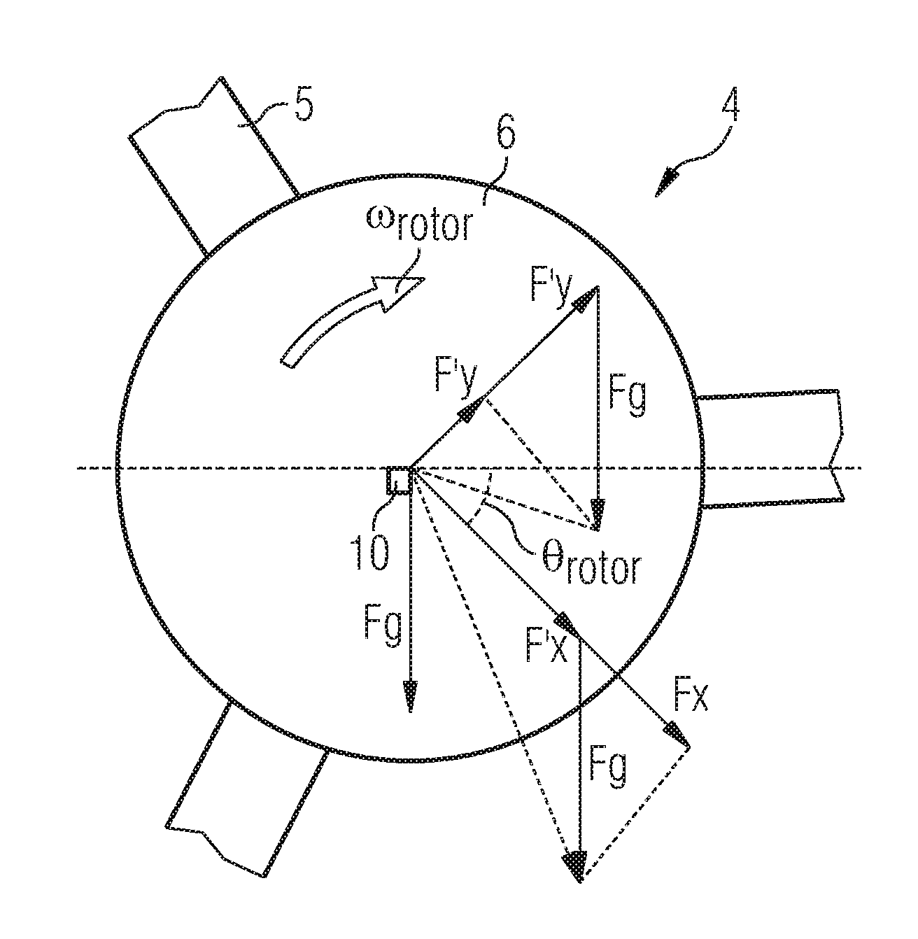
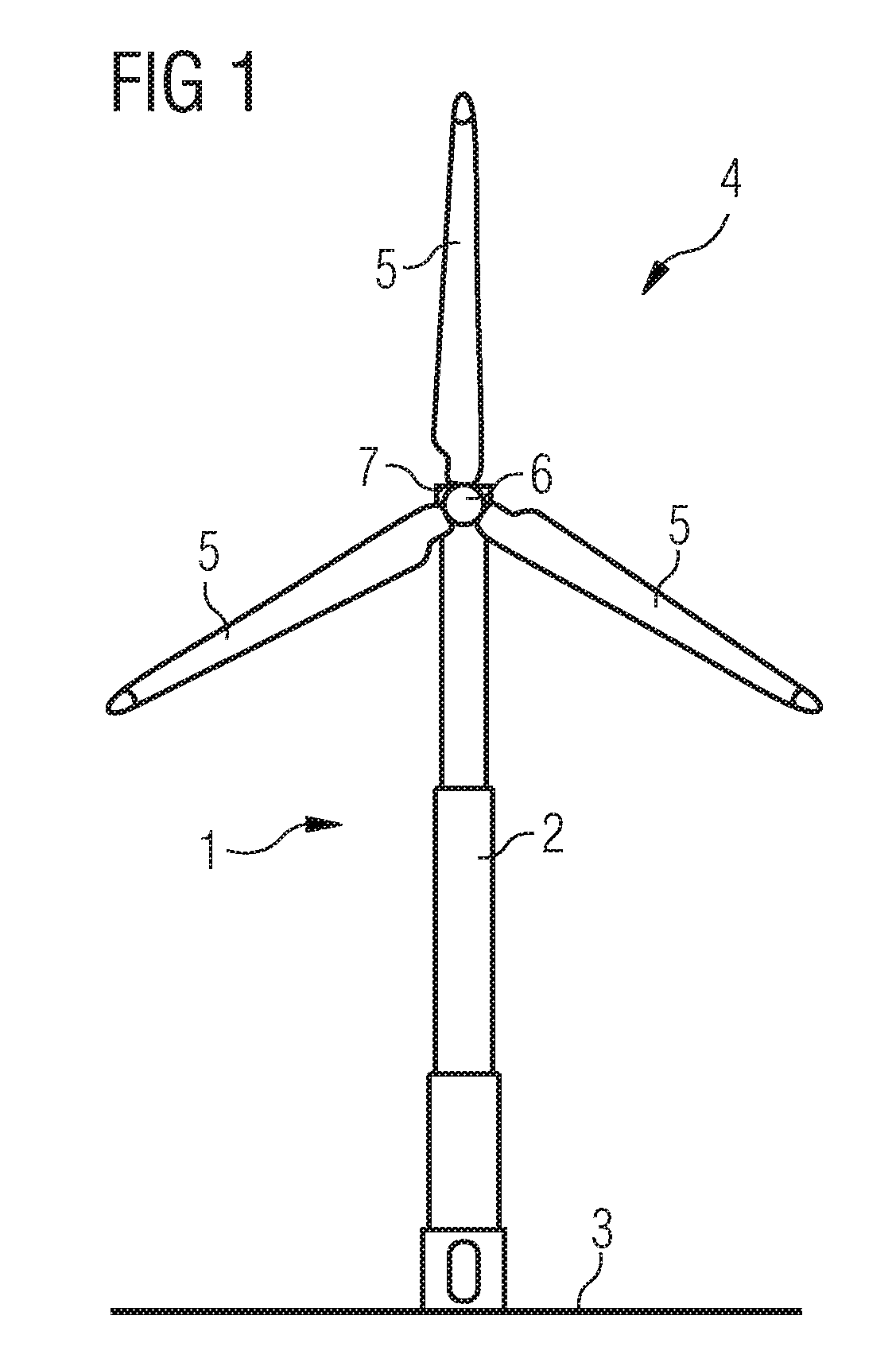
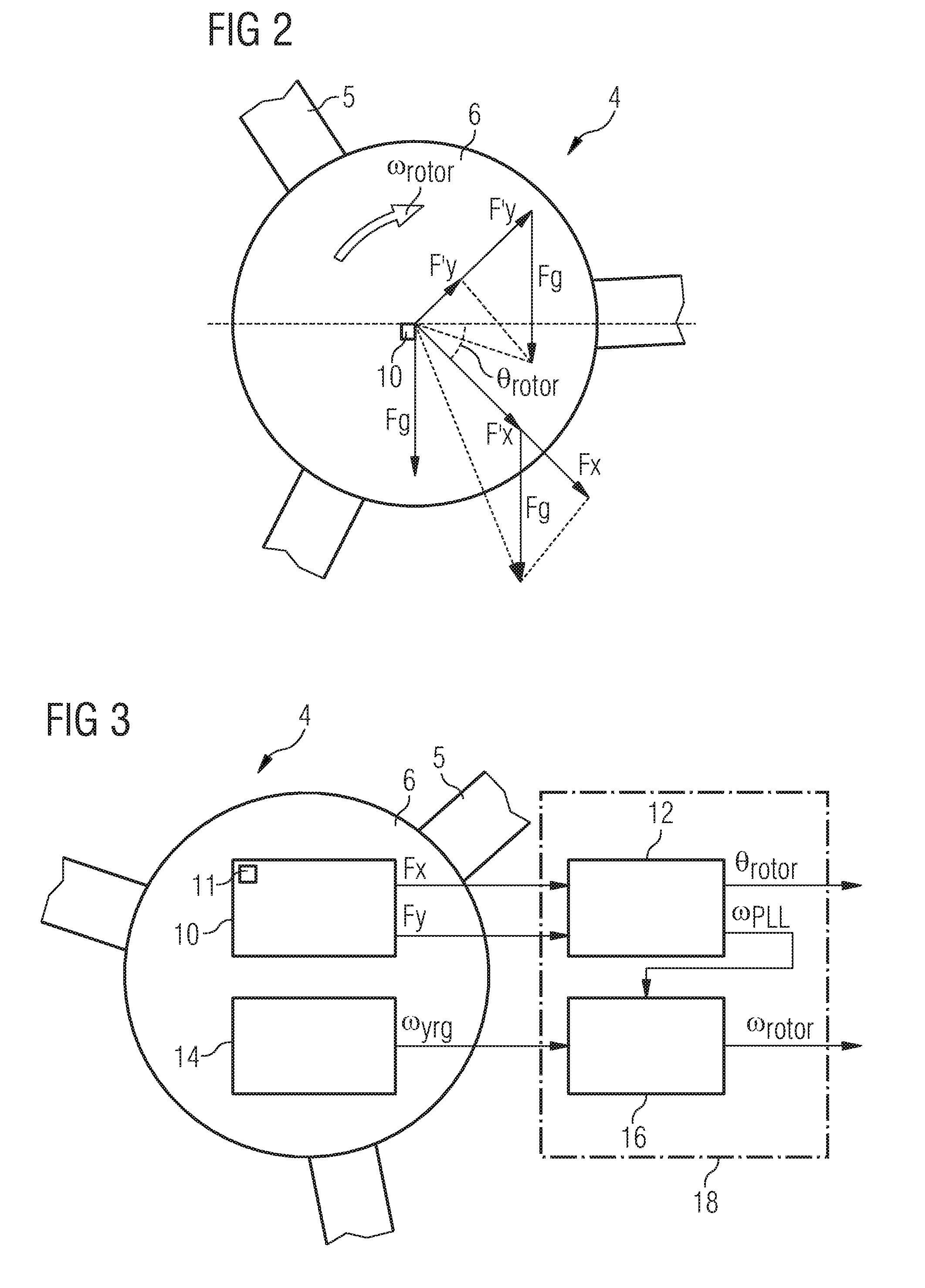
[0026]A typical wind turbine is shown in FIG. 1. The wind turbine 1 comprises a tower 2 which rests on a fundament in the ground 3 and at the top of the tower, a rotor 4. In the pre-sent embodiment, the rotor is equipped with three rotor blades 5 which are suspended in a rotor hub 6 which in turn is anchored in a nacelle 7 located at the top of the tower 2. Although the wind turbine 1 shown in FIG. 1 rests on the ground it is also possible that it rests on a platform anchored in the seabed. Moreover, although the rotor 4 in FIG. 1 has three rotor blades 5 it may have any number of rotor blades, i.e. at least one rotor blade. However, rotors with two and in particular with three rotor blades are most commonly used.

[0027]For a control of the wind turbines 1 operations it is desirable to know the rotation speed and the phase of the rotor 4 in a global frame of references so that errors in establishing rotor speed and phase due to movements of the top of the tower 2 can be avoided. A me...


PUM


Abstract

A method of determining at least one rotation parameter of a wind turbine rotor rotating with a rotation speed and a phase is provided. The method comprises the steps of: measuring an effective centrifugal force acting in a first pre-determined direction, which is defined in a co-ordinate system rotating synchronously with the rotor, on at least one reference object located in or at the rotor, establishing a first angular frequency representing the rotation speed of the rotor on the basis of variations in the measured effective centrifugal force due to gravitational force, establishing a second angular frequency representing the rotation speed of the rotor by use of at least one yaw rate gyro, and establishing the value of the rotation speed as the rotational parameter by correcting the second angular frequency by comparing it to the first angular frequency.

Description

CROSS REFERENCE TO RELATED APPLICATIONS[0001]This application is the US National Stage of International Application No. PCT / EP2007 / 050041, filed Jan. 3, 2007 and claims the benefit thereof. The International Application claims the benefits of European application No. 06005334.5 filed Mar. 15, 2006, both of the applications are incorporated by reference herein in their entirety.FIELD OF INVENTION[0002]The present invention relates to a wind turbine and method of determining at least one rotational parameter, such as rotation speed and phase of a wind turbine rotor.BACKGROUND OF THE INVENTION[0003]Wind turbines are used to produce electrical power from the energy contained in blowing wind. The wind turbine comprises a rotor which is driven by the wind and which in turn drives an induction generator, which usually is an AC generator.[0004]When the wind turbine is connected to a utility grid which requires a certain frequency, e.g. 50 Hz in Europe, the electrical power output of the win...

Claims


Application Information

Patent Timeline
Patent Type & Authority Patents(United States)
IPC IPC(8): F03B3/12
CPCF03D11/0091G01P3/16G01P3/22G01P3/44G01P21/02F05B2260/821F05B2270/101F05B2270/327F05B2270/329F05B2270/807Y02E10/722F03D17/00
Inventor EGEDAL, PER
Owner SIEMENS GAMESA RENEWABLE ENERGY AS
Why Eureka
Try Eureka