Joint optimisation of supply and bias modulation
a bias modulation and supply optimization technology, applied in the field of amplification of radio frequency (rf) signals, can solve problems such as limiting the usefulness of a dual bias architecture, and achieve the effect of optimizing system performance objectives
- Summary
- Abstract
- Description
- Claims
- Application Information
AI Technical Summary
Benefits of technology
Problems solved by technology
Method used
Image
Examples
first embodiment
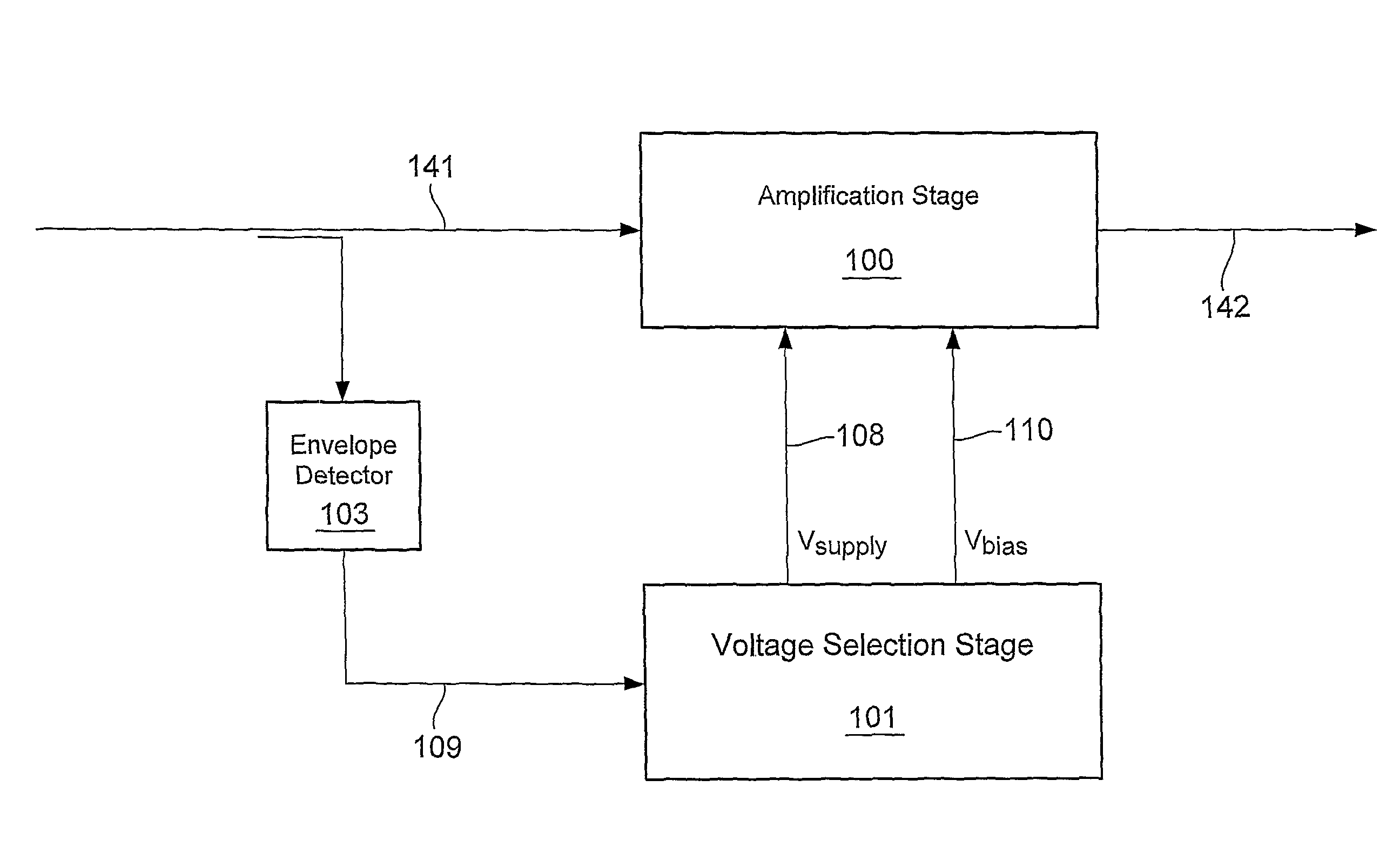
[0085]An arrangement in accordance with the invention is now described with reference to FIG. 14. Elements of this Figure which correspond to elements shown in FIG. 1 are identified by like reference numerals. FIG. 14 illustrates an embodiment in which the invention is implemented in the analogue domain.
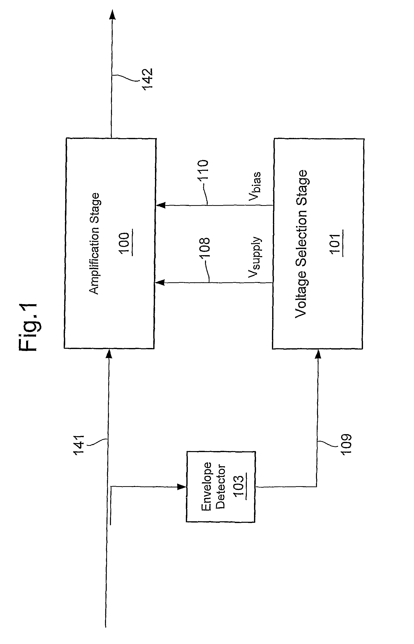
[0086]In the embodiments of FIG. 14, and subsequent embodiments described herein, there is shown an amplification stage 100 comprising a single RF amplifier. It should be understood, as discussed hereinabove, that the invention is not limited to any specific amplifier arrangement.
[0087]In the arrangement of FIG. 14 the amplifier 100 receives an RF input signal at a first input port on line 141, a continuously variable amplifier supply voltage on a line 108 at a second input port, and an amplifier bias voltage on line 110 at a third input port. The amplifier generates an RF output signal on line 142 at an output port.
[0088]The RF amplifier is fed with a non-constant envelope signal (e...
second embodiment
[0094]An arrangement in accordance with the invention is now described with reference to FIG. 15. Elements of this Figure which correspond to elements shown in FIGS. 1 and 13 are identified by like reference numerals. FIG. 15 illustrates an embodiment in which the invention is illustrated in the digital domain.
[0095]In this embodiment, envelope detection is performed in the digital domain. Similarly, the non-linear mappings for supply and bias voltages are also carried out in the digital baseband. One advantage of this embodiment is the ease of implementing delay elements in the digital domain, which males it easier to obtain precise time alignment between the RF envelope input signal and the amplifier supply and bias voltages.
[0096]The amplifier supply voltage on line 109 provided by the output of the DC-DC converter 102 on line 109. The DC-DC converter 102 is controlled by an output on line 112 from a non-linear mapping entity 116. The amplifier bias voltage on line 110 is provide...
third embodiment
[0101]In practice, the implementation of any embodiment in accordance with the invention will be in either the analogue domain as illustrated by the example of FIG. 14, or the digital domain as illustrated by the example of FIG. 15. However in a third embodiment, as illustrated by FIG. 16, the analogue and digital arrangements may be provided in parallel. Elements of this Figure which correspond to elements shown in any previous Figure are identified by like reference numerals. FIG. 16 illustrates an arrangement in which the invention is implemented in either the analogue or digital domain.
[0102]For the purpose of illustration in FIG. 16 a switch 112 is shown which selects between the Output of the non-linear digital mapping element 116 or the output of the non-linear analogue mapping element 104, and provides the selected output to the DC-DC converter 102. Similarly a switch 114 is provided which selects either the output of the non-linear digital mapping element 138 or the output ...
PUM
 Abstract
Description
Claims
Application Information
 - R&D
- Intellectual Property
- Life Sciences
- Materials
- Tech Scout
- Unparalleled Data Quality
- Higher Quality Content
- 60% Fewer Hallucinations
Browse by: Latest US Patents, China's latest patents, Technical Efficacy Thesaurus, Application Domain, Technology Topic, Popular Technical Reports.
© 2025 PatSnap. All rights reserved.Legal|Privacy policy|Modern Slavery Act Transparency Statement|Sitemap|About US| Contact US: help@patsnap.com


