
IC having TSV arrays with reduced TSV induced stress

a technology of tsv arrays and tsv arrays, which is applied in the direction of semiconductor devices, semiconductor/solid-state device details, electrical apparatus, etc., can solve the problems of significant thermally induced stress in silicon, adversely affecting performance (e.g. speed), and the fracture of the substrate containing the tsv array near the corner of the array, so as to achieve a larger operating temperature range, reduce resistance, and increase the effect of area

Active Publication Date: 2012-01-17
TEXAS INSTR INC
View PDF6 Cites 40 Cited by
  • Summary
  • Abstract
  • Description
  • Claims
  • Application Information

AI Technical Summary

Benefits of technology

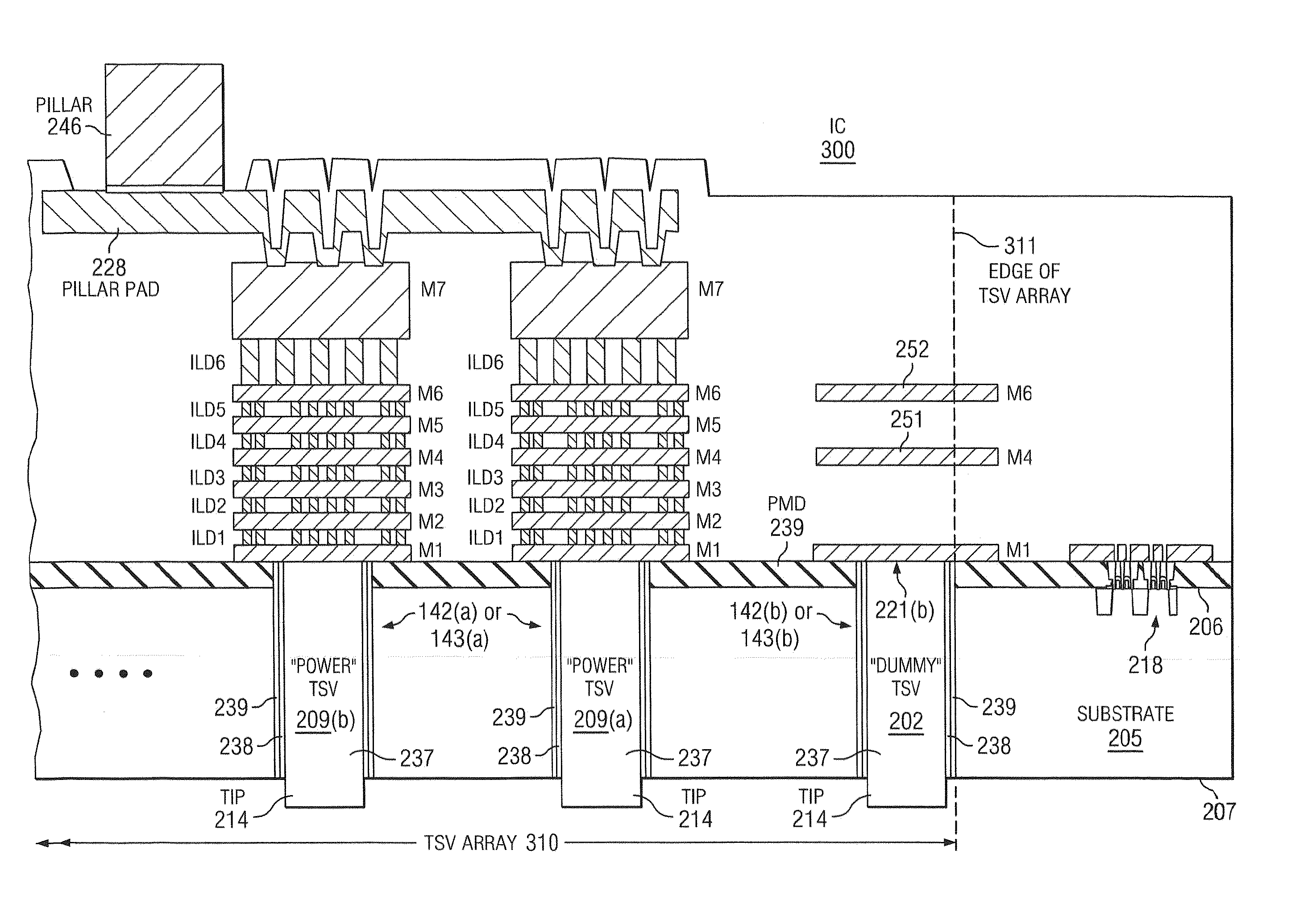
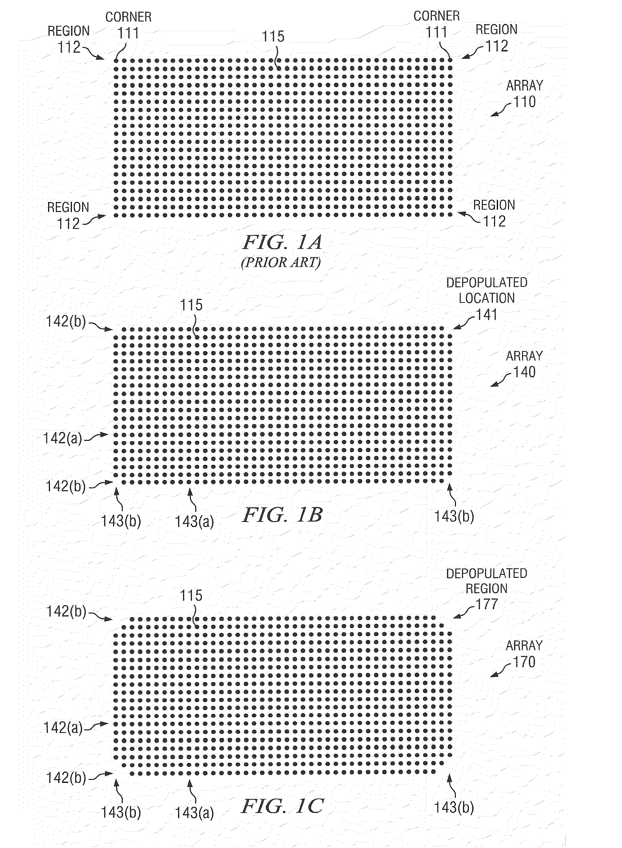
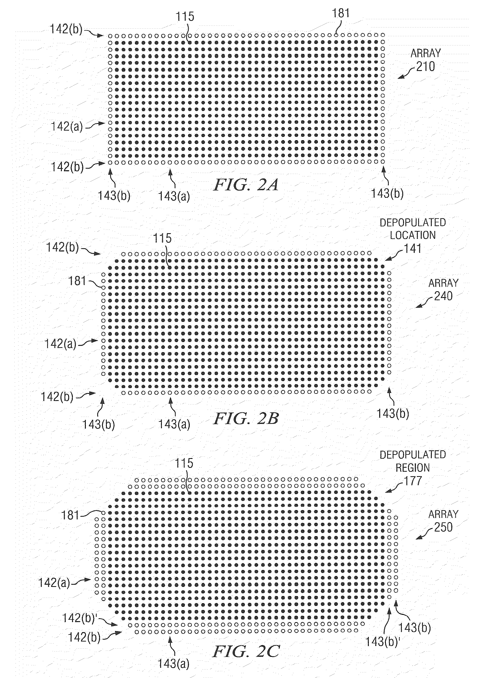
The patent text discusses a problem with traditional TSV arrays in ICs. These arrays have a large difference in expansion between the metal and the substrate, which causes stress on the surrounding substrate and can lead to fractures and reliability issues. The patent proposes a new design with rows and columns of TSVs, where some of the TSVs are removed from the corners of the array or replaced with non-functioning dummy TSVs to absorb the stress. This design allows for a larger area and operating temperature range for the IC, and can avoid the use of higher resistivity TSV metal.

Problems solved by technology

For example, copper has a CTE of approximately 17 ppm / ° C., whereas silicon has a CTE of approximately 2 to 3 ppm / ° C. This CTE mismatch (ΔCTE) can result in significant thermally induced stress in the silicon including the circuitry (e.g. MOS transistors) in the silicon surrounding the TSVs, particularly during certain fab processing subsequent to the fabrication of the TSV (e.g., 360 to 410° C. sinters), during assembly and test / operations as may occur during solder reflow (e.g., up to about 260° C.) or during thermo-compressive bonding (e.g., up to 400° C.
Stress induced fractures of the substrate containing the embedded TSVs during temperature cycling has led to reliability problems and has caused some designs to use tungsten TSVs to reduce the CTE differential which reduces cracking but also adversely affects performance (e.g. speed) of the IC due to an approximately 5× increase in resistivity compared to copper TVSs.
In worst-cases, this can lead to fracture of the substrate containing the TSV array near the corner of the array or failure of one or more bonds involving the TSVs, such as at the TSV tip comprising bonds to a die mounted above.
Such stress fields can cause the bonds involving the TSV tips at the periphery regions of embedded TSV arrays to fail, due to open or high resistance contacts at the TSV tip bonding locations.

Method used


Image

  • IC having TSV arrays with reduced TSV induced stress
  • IC having TSV arrays with reduced TSV induced stress
  • IC having TSV arrays with reduced TSV induced stress

Examples


Embodiment Construction

[0016]Disclosed embodiments are described with reference to the attached figures, wherein like reference numerals are used throughout the figures to designate similar or equivalent elements. The figures are not drawn to scale and they are provided merely to illustrate the disclosed embodiments. Several aspects are described below with reference to example applications for illustration. It should be understood that numerous specific details, relationships, and methods are set forth to provide a full understanding of the disclosed embodiments. One having ordinary skill in the relevant art, however, will readily recognize that the disclosed embodiments can be practiced without one or more of the specific details or with other methods. In other instances, well-known structures or operations are not shown in detail to avoid obscuring the disclosed embodiments. The disclosed embodiments are not limited by the illustrated ordering of acts or events, as some acts may occur in different orde...


PUM


Abstract

An integrated circuit (IC) includes a substrate having a top side having active circuitry thereon including a plurality of metal interconnect levels including a first metal interconnect level and a top metal interconnect level, and a bottom side. At least one TSV array includes a plurality of TSVs. The TSVs are positioned in rows including a plurality of interior rows and a pair of exterior rows and a plurality of columns including a plurality of interior columns and a pair of exterior columns. At least a portion of the TSVs in the array are electrically connected TSVs that are coupled to a TSV terminating metal interconnect level selected from the plurality of metal interconnect levels. At least one of the exterior rows or exterior columns include a lower number of electrically connected TSVs compared to a maximum number of electrically connected TSVs in the interior rows and interior columns, respectively.

Description

CROSS REFERENCE TO RELATED APPLICATIONS[0001]This application claims the benefit of Provisional Application Ser. No. 61 / 141,136 entitled “Method for Reducing Stress Imparted to Integrated Circuits by Through Silicon Vias (TSVs), filed Dec. 29, 2008, which is herein incorporated by reference in its entirety.FIELD[0002]Disclosed embodiments generally relate to IC devices having through-substrate vias.BACKGROUND[0003]Vias are routinely used in forming ICs. Vias may be formed that extend vertically from the bottom side of an IC die to one of the metal interconnect layers on the active top side of the IC die. Such structures are often referred to as “through-silicon vias”, and are referred to more generally herein as through-substrate vias (TSVs).[0004]TSVs are generally framed by a dielectric liner and filled with copper or another electrically conductive TSV filler material to provide the desired low resistance vertical electrical connection. A diffusion barrier metal formed on the die...

Claims


Application Information

Patent Timeline
Patent Type & Authority Patents(United States)
IPC IPC(8): H01L23/48H01L23/52H01L29/40
CPCH01L23/481H01L2924/0002H01L2924/00
Inventor WEST, JEFFREY ALANSIMMONS-MATTHEWS, MARGARET ROSEAMAGAI, MASAZUMI
Owner TEXAS INSTR INC
Learn More