Diffraction free, self-bending airy wave arrangement

Active Publication Date: 2012-01-24
UNIV OF CENT FLORIDA RES FOUND INC
View PDF9 Cites 35 Cited by
  • Summary
  • Abstract
  • Description
  • Claims
  • Application Information

AI Technical Summary

Benefits of technology

[0017]A fourth objective of the invention is to provide methods, apparatus and systems for Airy waves are highly asymmetric and as a result their energy is more tightly confined in one quadrant thus increasing the energy density in the main lobe(s). Importantly these wavepackets can be one, two, and three-dimensional waves. In addition they tend t

Problems solved by technology

Therefore, for all practical purposed, it is difficult to synthesize such beams unless of course they are amplitude truncated.
Yet, finite power Airy wave packets have never been investigated under linear conditions.
However, the publication does not teach, and thus is not enabling in regard to methods or systems for implementing Airy wave packets in dispersive optical fibers.
Of co

Method used


Image

  • Diffraction free, self-bending airy wave arrangement
  • Diffraction free, self-bending airy wave arrangement
  • Diffraction free, self-bending airy wave arrangement

Examples


Embodiment Construction

[0046]Before explaining the disclosed embodiments of the present invention in detail it is to be understood that the invention is not limited in its application to the details of the particular arrangements shown since the invention is capable of other embodiments. Also, the terminology used herein is for the purpose of description and not of limitation.

[0047]The following is a list of the reference numbers used in the drawings and the detailed specification to identify components:

[0048]

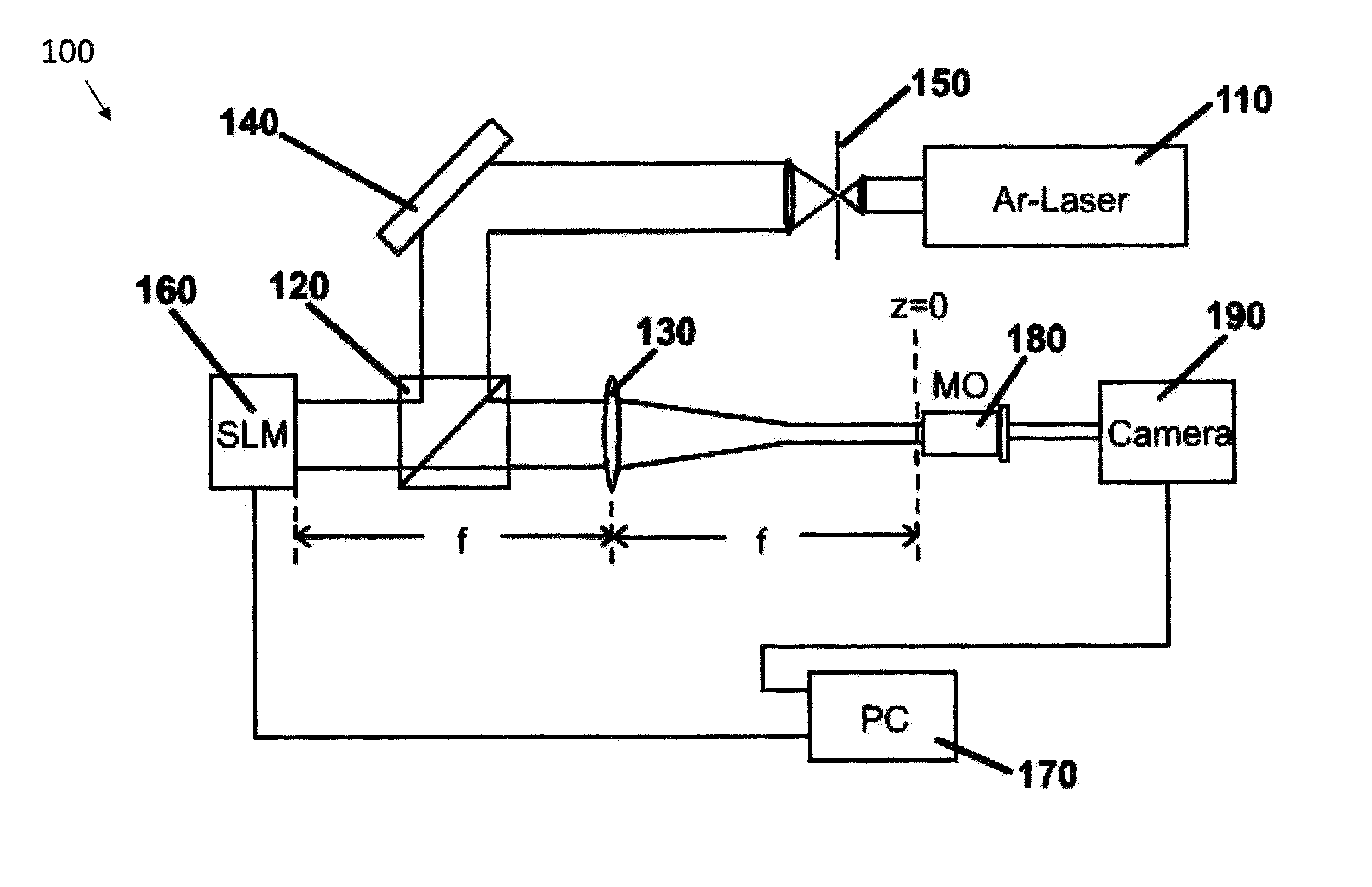
100experimental set-up110laser120beam splitter910input wave130lens920cubic phase140mirror925Fourier transform device150beam expander930Airy wave160spatial light modulator1010input beam170controller1020amp-phase filter180MO1030Airy pattern output190camera1110input pulse810input beam1020cubic spectral phase860airy pattern output1130Airy pulse output

[0049]The present invention provides methods and systems to generate Airy waves and provides examples of their possible applications using unique and remark...


PUM


Abstract

Methods and systems for Airy waves and Airy wavepackets or Airy beam generation from an input beam or pulse. Airy wavefronts and Airy wavepackets can be generated using Airy beam generation through Fourier synthesis using phase masks or filters in the spatial domain; Airy beam generation using amplitude and phase filters in the spatial domain; and Airy pulse generation through Fourier synthesis using phase and/or amplitude filters in the temporal frequency domain. The Airy waves are highly asymmetric and as a result their energy is more tightly confined in one quadrant thus increasing the energy density in the main lobes. These wavepackets can be one, two, and three-dimensional waves. In addition they tend to self-heal themselves which is important in adverse environments.

Description

[0001]This application claims the benefit of priority to U.S. Provisional Application No. 61 / 047,512 filed on Apr. 24, 2008.FIELD OF THE INVENTION[0002]This invention relates to wave transmission and, in particular, to methods, apparatus and systems for generating diffraction free Airy waves and wavepackets that propagate over relatively long distances without any appreciable broadening and or spreading-effects for application including optics, acoustics, microwaves, in particle manipulation and detection, biology, cold atom optics, and in material processing.BACKGROUND AND PRIOR ART[0003]Diffraction-free beams are by definition localized optical wave packets that remain invariant during propagation. Perhaps the best known example of such a diffraction-free wave is the Bessel beam first predicted theoretically and experimentally demonstrated by Durnin, J. J. Opt Soc. Am. A 4, p. 651 (1987) and Durnin, et al. Phys. Rev. Lett. 58, p. 1499 (1987). Other such non-diffracting wave config...

Claims


Application Information

Patent Timeline
IPC IPC(8): G02B27/56H05H3/04G21K1/06
CPCG02B27/56
Inventor CHRISTODOULIDES, DEMETRIOS N.DOGARIU, ARISTIDESIVILOGLOU, GEORGIOS
Owner UNIV OF CENT FLORIDA RES FOUND INC
Why Eureka
Try Eureka