
Media for high density perpendicular magnetic recording

Active Publication Date: 2012-02-07
SEAGATE TECH LLC
View PDF137 Cites 18 Cited by
  • Summary
  • Abstract
  • Description
  • Claims
  • Application Information

AI Technical Summary

Benefits of technology

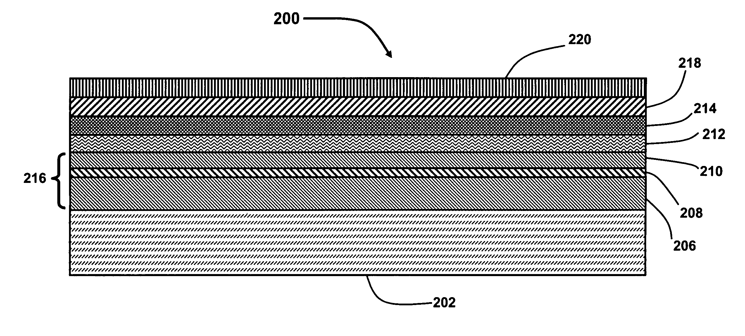
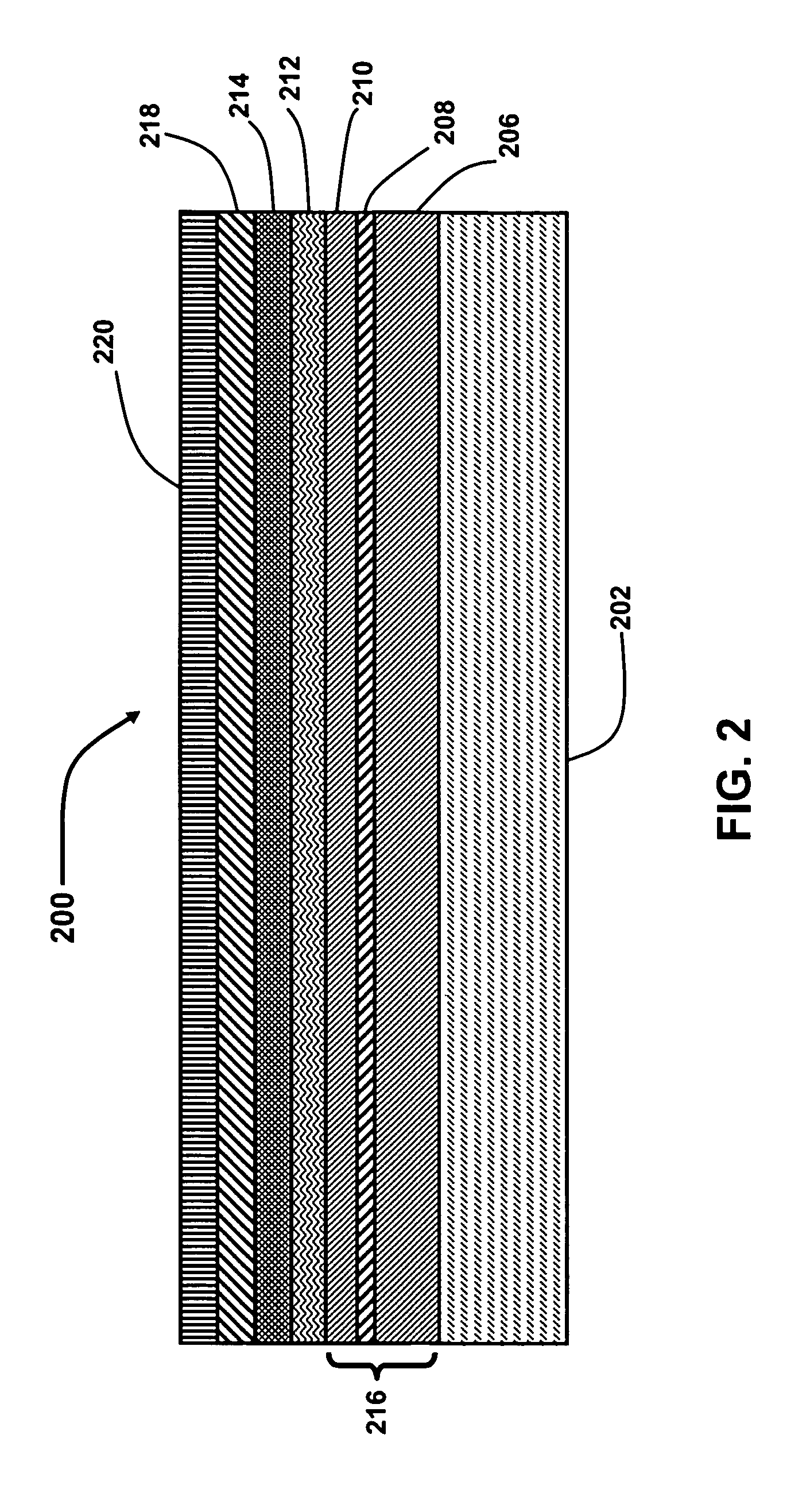
[0017]According to the present invention, a perpendicular magnetic recording medium comprising a high magnetization (Ms) and low anisotropy (Ku) capping layer is provided for the purpose of improving resolution, SNR, and thermal stability. The recording medium with a high Ms capping layer can reduce DC noise by introducing intergranular exchange coupling between the magnetic capping layer and underlying magnetic recording layers, which prevents small grains in the magnetic recording layer from magnetization reversals, while low transition jitter is maintained by the well isolated Co grains with high Ku.
[0020]According to another aspect, the perpendicular magnetic recording layer and the magnetic capping layer are magnetically exchange coupled. Accordingly, the magnetic capping layer substantially prevents grains in the perpendicular magnetic recording layer that are smaller than an average grain size from experiencing magnetization reversals. According to one aspect, the magnetic grains include a CoCr alloy, such as a CoCrPt alloy. The grain boundary phase can be an oxide phase, such as a Cr-oxide phase. According to one aspect, the magnetic grains have an average grain size of not greater than about 10 nanometers, such as from about 5 nanometers to about 7 nanometers. The capping layer can also have a lower thermal stability factor (KuV) than the perpendicular magnetic recording layer.

Problems solved by technology

However, as the grain size is reduced, thermal fluctuations can cause the magnetic domains to “flip”, causing a loss of magnetization over a period of time.
However, the large write head gaps that are needed for good overwrite of high coercivity media lead to excessive fringing, negatively affecting the data written on adjacent tracks.
However, the fabrication of well-isolated Co grains with high anisotropy is difficult because the magnetic grain size, as well as the degree of grain boundary segregation, is highly dependent upon the level of oxidation.
Moreover, variations in the degree of grain boundary segregation within the magnetic layer result in a distribution of exchange fields and magnetic cluster size, which increases transition jitter.
Transition jitter is a major component of medium noise, which is a limiting factor in increasing the recording density of magnetic recording media.

Method used


Image

  • Media for high density perpendicular magnetic recording
  • Media for high density perpendicular magnetic recording
  • Media for high density perpendicular magnetic recording

Examples


examples

[0058]In the following examples, media are formed by depositing material layers onto NiP-plated aluminum substrates using an Intevac MDP250B system. Ta / Ru is used as an intermediate layer. CoPtCrO magnetic recording layers are dc-magnetron sputtered using an oxygen-doped CoPtCr target. Two CoPtCrO alloys with an Ms of 330 and 390 emu / cm3 are used as the magnetic recording layers. Their combined thicknesses and magnetic coercivities (Hc) are 14 to 17 nanometers and 4 to 5 kOe without a magnetic capping layer. Various Co-alloy capping layers with Ms in the range of 190 emu / cm3 to 900 emu / cm3 are deposited onto the CoPtCrO magnetic recording layer. The soft magnetic underlayer is made of two antiferromagnetically coupled layers of CoZrTa with a total thickness of 85 nm.

[0059]The magnetic capping layer with an Ms of 190 emu / cm3 has a higher concentration of Cr and B (non-magnetic elements) than the magnetic capping layer with higher Ms values, resulting in a more segregated grain struct...


PUM


Abstract

Perpendicular magnetic recording media having a magnetic capping layer that is exchange coupled to an underlying perpendicular magnetic recording layer. The magnetic coupling layer is a granular layer having a high saturation magnetization (Ms). The perpendicular magnetic recording layer can include magnetic grains separated by an oxide grain boundary phase.

Description

CROSS-REFERENCE TO RELATED APPLICATIONS[0001]This patent application claims priority under 35 U.S.C. §119(e) from U.S. Provisional Patent Application Ser. No. 60 / 658,904 entitled “CoPtCrO COMPOSITE MEDIA FOR HIGH DENSITY PERPENDICULAR RECORDING,” filed on Mar. 4, 2005, the entire disclosure of which is incorporated herein by reference in its entirety.BACKGROUND OF THE INVENTION[0002]1. Field of the Invention[0003]The present invention is directed to a perpendicular magnetic recording medium. In particular, the present invention is directed to a perpendicular magnetic recording medium that includes a structurally discontinuous magnetic capping layer over a perpendicular magnetic recording layer for improved magnetic recording properties, including an increased signal-to-noise ratio (SNR), improved thermal stability and reduced transition jitter.[0004]2. Description of Related Art[0005]Thin film magnetic recording media are composed of multiple layers, including one or more magnetic r...

Claims


Application Information

Patent Timeline
IPC IPC(8): G11B5/66
CPCG11B5/65G11B5/66G11B5/672
Inventor CHOE, GUNNACHARYA, B. RAMAMURTHYZHENG, MINABARRA, E. NOEL
Owner SEAGATE TECH LLC
Learn More