System and method for fast approximate focus

a technology of automatic focus and machine vision, applied in the field of machine vision inspection systems, to achieve the effect of improving or maximizing throughpu

Active Publication Date: 2012-02-07
MITUTOYO CORP
View PDF23 Cites 188 Cited by
  • Summary
  • Abstract
  • Description
  • Claims
  • Application Information

AI Technical Summary

Benefits of technology

[0008]In contrast to each of the previously described known systems and methods for performing autofocus operations, the present invention provides improved inspection throughput by using fast approximate autofocusing suitable for certain operations in a general purpose precision machine vision inspection system. The terms “fast approximate autofocusing” and “fast approximate focusing” are generally used interchangeably herein, and may be taken to mean the same thing unless otherwise indicated. Some advantageous features of the methods include that they may be implemented to improve throughput for machines already in the field, and that they do not require a special focus sensor. According to one aspect of the invention, a general method is provided for implementing fast approximate autofocus operations during learn mode (e.g., in one embodiment by training a fast approximate autofocus video tool). In general, a set of learn mode operations are provided for determining a representative focus curve and a related focus threshold value, given an image of a representative region of interest (ROI). In one embodiment, learn mode fast approximate autofocus learning or “tool training” operations include acquiring a representative image of the representative region of interest. The region of interest may be defined using a video tool user interface, for example, and generally includes a representative feature to be inspected. For the purposes of creating a part program, the representative feature represents corresponding features on other workpieces. Then, a representative feature-specific focus curve is determined for the region of interest (ROI). The feature-specific focus curve, which characterizes image focus for the ROI as a function of the Z-coordinate used for imaging, may be determined by conventional methods during learn mode. Then, a focus threshold value, corresponding to a level of “approximate focus” that is sufficient for supporting the desired feature inspection operations, is determined and / or learned. (In this context, “learned” may mean determined and recorded, in some form, in a part program (e.g., as a video tool parameter) as a basis for later automatic inspection of corresponding features.) More generally, the determined and / or learned representative feature-specific focus curve data and / or the focus threshold value data may be characterized and recorded in any convenient form. In one embodiment, the “curve data” may correspond to a conventional form of a focus curve, and the “value data” may correspond to a standard threshold value. In other embodiments, the curve data may correspond to other types of data, such as a dense focus curve “F-Z” lookup table, coefficients that customize a nominal analytical curve shape, a pruned lookup table, etc. Similarly, in other embodiments the threshold data may correspond to other types of data, such as “depth of field (DOF) units” that are used cooperatively with the curve data to compute the numerical value at run mode, a numerical value computed and stored at learn time, a multiplication factor (e.g., a fraction) for the focus curve peak height, etc.
[0009]In accordance with another aspect of the invention, a general method for implementing fast approximate autofocus operations during run mode (e.g., by executing the operations of a fast approximate autofocus video tool) is provided. In general, a set of run mode operations are provided for employing representative focus curve data and focus threshold value data to confirm or provide a fast approximate focus for an image to be used for inspecting a workpiece feature. In general, the representative focus curve data and focus threshold value data will have been previously established for a corresponding feature in a corresponding workpiece, such as during a learn mode. Such use of a fast approximate focus provides an acceptable level of accuracy in many applications where the inspection operation does not require accurate Z coordinate data. For example, using appropriate image processing, various XY edge location measurements may remain relatively accurate and repeatable even when they are determined from an inspection image which includes image blur (e.g., an image that is only approximately in focus).
[0013]It should be appreciated that performing a subsequent adjustment or search in the same direction as the last (previous) successful adjustment direction is advantageous when a part that is being inspected is nominally flat (or nearly so), but is tilted or warped on the stage of the machine vision system. When inspecting an array of features on such parts (e.g., printed circuit board holes), the slope is likely to be consistent, or at least slowly changing, such that an a focus adjustment direction that was successful during the inspection of the previous workpiece feature will likely be the correct focus adjustment direction for the next workpiece feature. Therefore, this method is likely to improve or maximize throughput when inspecting such workpieces.

Problems solved by technology

Due to increasing computation speeds, computation speeds are becoming less relevant to inspection throughput, while the physical movements required for the systems and methods referred to above generally remain as a primary factor limiting inspection throughput.

Method used


Image

  • System and method for fast approximate focus
  • System and method for fast approximate focus
  • System and method for fast approximate focus

Examples


Embodiment Construction

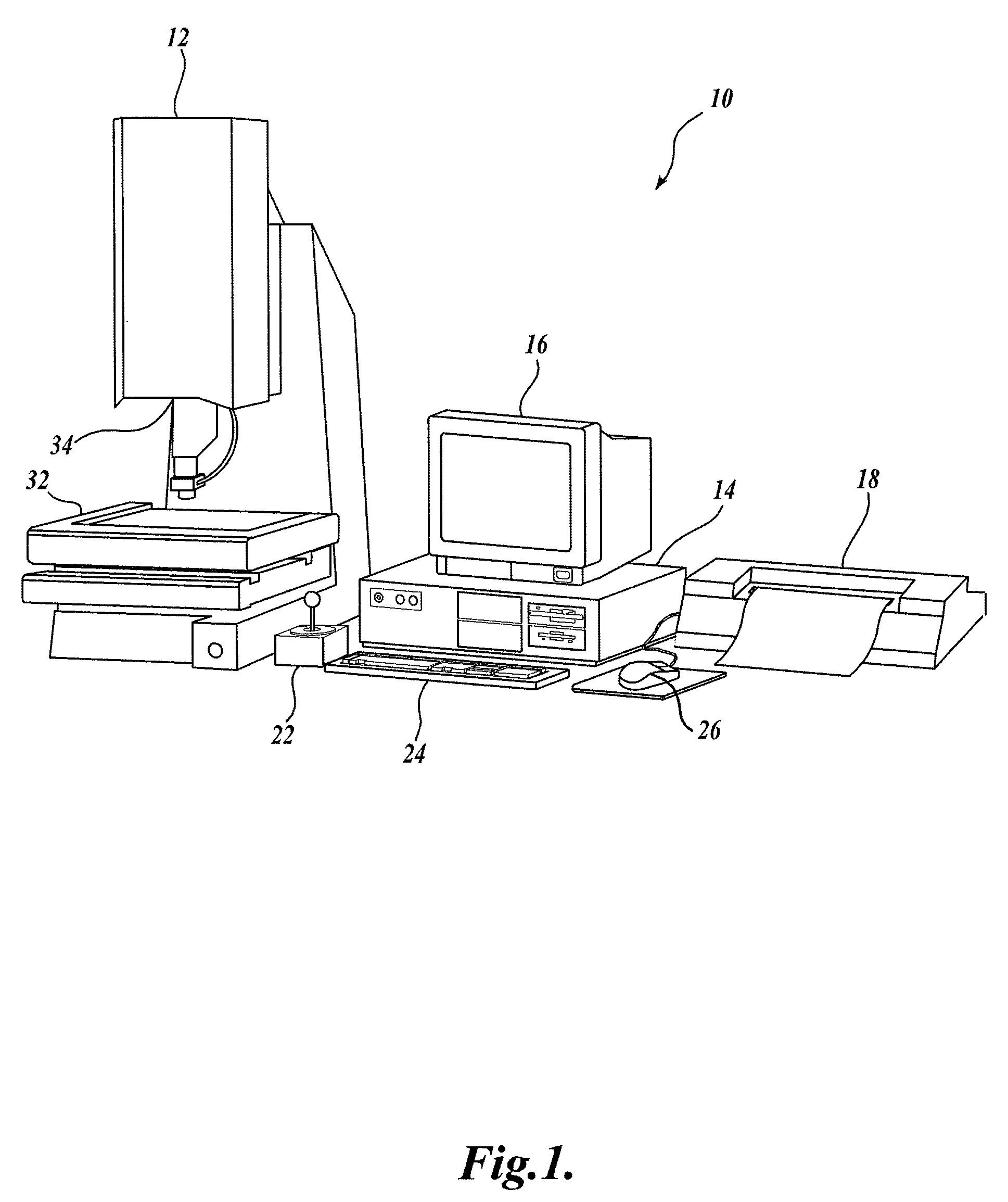
[0025]FIG. 1 is a block diagram of one exemplary machine vision inspection system 10 usable in accordance with the present invention. The machine vision inspection system 10 includes a vision measuring machine 12 that is operably connected to exchange data and control signals with a controlling computer system 14. The controlling computer system 14 is further operably connected to exchange data and control signals with a monitor or display 16, a printer 18, a joystick 22, a keyboard 24, and a mouse 26. The monitor or display 16 may display a user interface suitable for controlling and / or programming the operations of the machine vision inspection system 10.

[0026]The vision measuring machine 12 includes a moveable workpiece stage 32 and an optical imaging system 34 which may include a zoom lens or interchangeable lenses. The zoom lens or interchangeable lenses generally provide various magnifications for the images provided by the optical imaging system 34. The machine vision inspect...


PUM


Abstract

Fast approximate focus operations providing an approximately focused image that is sufficiently focused to support certain subsequent inspection operations. The operations are particularly advantageous when used to provide images for successive inspection operations that predominate when inspecting planar workpieces. Improved inspection throughput is provided because, in contrast to conventional autofocus operations, the fast approximate focus operations do not acquire an image stack during a run mode as a basis for determining a best focused image. Rather, during learn mode, a representative feature-specific focus curve and a focus threshold value are determined and used during run mode to provide an approximately focused image that reliably supports certain inspection operations. In one embodiment, an acceptable approximately focused inspection image is provided within a limit of two focus adjustment moves that provide two corresponding images. The adjustment moves are based on the representative feature-specific focus curve provided in learn mode.

Description

FIELD OF THE INVENTION[0001]The invention relates generally to machine vision inspection systems, and more particularly to systems and methods for automatically focusing a machine vision inspection system.BACKGROUND OF THE INVENTION[0002]Precision machine vision inspection systems (or “vision systems” for short) can be utilized to obtain precise dimensional measurements of inspected objects and to inspect various other object characteristics. Such systems may include a computer, a camera and optical system, and a precision stage that is movable in multiple directions to allow workpiece inspection. One exemplary prior art system, that can be characterized as a general-purpose“off-line” precision vision system, is the commercially available QUICK VISION® series of PC-based vision systems and QVPAK® software available from Mitutoyo America Corporation (MAC), located in Aurora, Ill. The features and operation of the QUICK VISION® series of vision systems and the QVPAK® software are gene...

Claims


Application Information

Patent Timeline
Patent Type & Authority Patents(United States)
IPC IPC(8): G06K9/40
CPCG02B7/36G03B13/36H04N5/23212G01B11/24H04N23/673H04N23/631H04N23/635
Inventor BRYLL, ROBERT K.NAHUM, MICHAEL
Owner MITUTOYO CORP
Why Eureka
Try Eureka