
Tuning fork vibration device and method for manufacturing the same

a technology of vibration device and tuning fork, which is applied in the direction of basic electric elements, stringed musical instruments, instruments, etc., can solve the problems of difficult miniaturization of clock modules, and achieve the effect of being ready to manufactur

Active Publication Date: 2012-02-21
COLUMBIA PEAK VENTURES LLC
View PDF8 Cites 3 Cited by
  • Summary
  • Abstract
  • Description
  • Claims
  • Application Information

AI Technical Summary

Benefits of technology

"The present invention provides a small-sized tuning fork vibration device that can achieve a resonance frequency in the several tens kHz band. The device includes a semiconductor layer formed on a substrate, an oxide layer, and a driving section that generates flexural vibration of the vibration section. The vibration section includes a support section and two beam sections formed in a cantilever shape with the support section as a base of the beam sections. The driving section includes a pair of drivers formed on each of the two beam sections, each driver including a first electrode layer, a piezoelectric layer, and a second electrode layer. The resonance frequency of the vibration section can be at a 32 kHz band, which is suitable for a clock module. The piezoelectric layer is composed of lead zirconate titanate or a solid solution of lead zirconate titanate. The manufacturing method of the tuning fork vibration device is based on known MEMS technology."

Problems solved by technology

In order to obtain a resonance frequency at several tens kHz band, the arm-length of the beam needs to be several mm or greater, which causes a problem in that miniaturization of the clock module is difficult.

Method used


Image

  • Tuning fork vibration device and method for manufacturing the same
  • Tuning fork vibration device and method for manufacturing the same

Examples


Embodiment Construction

[0021]Preferred embodiments of the present invention are described below with reference to the accompanying drawings.

[0022]1. Tuning Fork Vibration Device

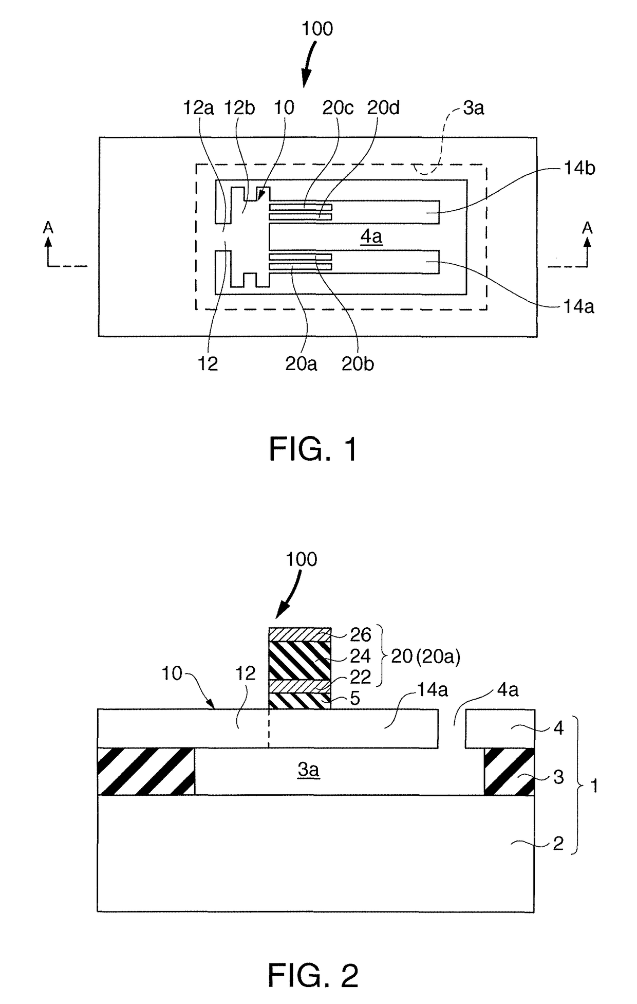
[0023]FIG. 1 is a plan view schematically showing the structure of a tuning fork vibration device 100 in accordance with an embodiment of the invention, and FIG. 2 is a cross-sectional view of the structure taken along lines A-A of FIG. 1.

[0024]As shown in FIG. 1, the tuning fork vibration device 100 includes a SOI substrate 1, a tuning fork type vibration section 10 formed in the SOI substrate 1, and a driving section 20 for generating flexural vibration of the vibration section 10.

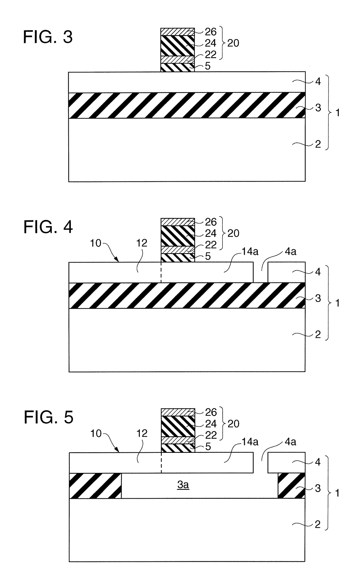
[0025]The SOI substrate 1 is formed from a silicon substrate 2, and an oxide layer (a silicon oxide layer) 3 and a silicon layer 4 successively laminated on the silicon substrate 2. The thickness of the silicon substrate 4 may preferably be 20 μm or less, so that the tuning fork vibration device 100 can be made smaller in size. The SOI substrate 1 may a...


PUM


Abstract

A tuning fork vibration device includes: a SOI substrate having a substrate, an oxide layer formed above the substrate and a semiconductor layer formed above the oxide layer; a tuning fork type vibration section that is formed by processing the semiconductor layer and the oxide layer and composed of the semiconductor layer; and a driving section for generating flexural vibration of the vibration section, wherein the vibration section includes a support section and two beam sections formed in a cantilever shape with the support section as a base of the beam sections, and the driving section includes a pair of drivers formed on each of the two beam sections, each of the drivers including a first electrode layer, a piezoelectric layer formed above the first electrode layer and a second electrode layer formed above the piezoelectric layer.

Description

[0001]The entire disclosure of Japanese Patent Application No. 2006-090254, filed Mar. 29, 2006 is expressly incorporated by reference herein.BACKGROUND[0002]1. Technical Field[0003]The present invention relates to a tuning fork vibration device having a tuning fork vibration section formed on a SOI substrate which is driven by vibration of a piezoelectric layer.[0004]2. Related Art[0005]The development of communication devices such as clocks, personal computers and the like is trending toward a reduction in size and a reduction in power consumption; and for this reason, a reduction in size and a reduction in power consumption of clock modules are demanded. As a vibration device that is used in an oscillator section of a clock module, a 32 kHz tuning fork vibration device is still used in order to take advantage of its conventional design resource and power saving property. The tuning fork vibration device has a structure in which a piezoelectric such as quartz that is processed in ...

Claims


Application Information

Patent Timeline
Patent Type & Authority Patents(United States)
IPC IPC(8): H01L21/00H01L41/08H01L41/09H01L41/187H01L41/22H01L41/332H03H3/007H03H9/24
CPCH03H9/21H03H2003/026
Inventor HIGUCHI, TAKAMITSUEGUCHI, MAKOTO
Owner COLUMBIA PEAK VENTURES LLC
Learn More