Slotting milling cutter for machining with a high feed and a low pass depth

a milling cutter and low pass depth technology, applied in the field of milling cutters, can solve the problems of damage to the part to be machined, the cutting head of the milling cutter to be detached, and the two-part milling cutter of the above type to have a major drawback, so as to reduce the shear force

Active Publication Date: 2012-02-28
SN DETUDE & DE CONSTR DE MOTEURS DAVIATION S N E C M A
View PDF16 Cites 6 Cited by
  • Summary
  • Abstract
  • Description
  • Claims
  • Application Information

AI Technical Summary

Benefits of technology

[0007]The subject of the invention is a slotting milling cutter of the aforementioned type, the dimensions and the geometry of which are particularly suitable for reducing the shear forces to which the soldered joint connecting the body to the head of the milling cutter is subjected during a machining operation.
[0012]Thanks to the combination of the geometric and dimensional characteristics of the milling cutter according to the invention, the cutting forces transmitted between the teeth and the part during machining result in low torsional forces in the milling cutter and in higher axial compressive forces to which the milling cutter is much less sensitive. The reduction in torsional forces in the milling cutter enables the shear forces in the brazed joint of the milling cutter to be reduced and therefore limits the risk of the head being torn off the body of the milling cutter.
[0013]The milling cutter according to the invention allows high-speed machining of parts made of very hard materials, such as for example an Inconel 718 wheel of a centrifugal turbomachine compressor. This milling cutter allows high cutting speeds and feeds to be achieved and increases the rate of material removal so as to reduce the time required to machine a part.
[0017]According to a third feature of the invention, the radial or lateral cutting angle γf, measured in the working plane perpendicular to the rotation axis of the milling cutter and passing through the point in question on the main edge, is negative so as to increase the robustness of the cutting edge and also to ensure good removal of the chips. This negative angle also makes it possible to have a compressive stress and not a tensile stress on the cutting edge when this edge approaches the end of the kerf and when the chip is ready to be detached from the part. The radial cutting angle γf is for example about −5°.
[0019]The milling cutter according to the invention therefore has a positive / negative geometry characterized by a positive axial cutting angle γp and by a negative radial cutting angle γf. This type of milling cutter can withstand very high cutting forces greater than those of a milling cutter having a double positive geometry. This positive / negative geometry also allows high machining speeds with high feeds, since the negative radial cutting angle increases the resistance of the cutting edge, and the positive axial cutting angle makes it easier to form the chips, directing them on the opposite side from the head of the milling cutter.
[0026]the flank and rake faces are joined to a side wall of the tooth via rounded edges having radii of curvature of between about 0.5 mm and 1 mm. These rounded edges increase the strength of the milling cutter and ensure more uniform distribution both of the heat and the wear;

Problems solved by technology

A two-part milling cutter of the aforementioned type nevertheless has a major drawback.
During a machining operation, the torsional forces applied on the cutting tool generate large shear forces in the brazed joint that may weaken it and cause the milling cutting head to be detached and may damage the part to be machined.

Method used


Image

  • Slotting milling cutter for machining with a high feed and a low pass depth
  • Slotting milling cutter for machining with a high feed and a low pass depth
  • Slotting milling cutter for machining with a high feed and a low pass depth

Examples


Embodiment Construction

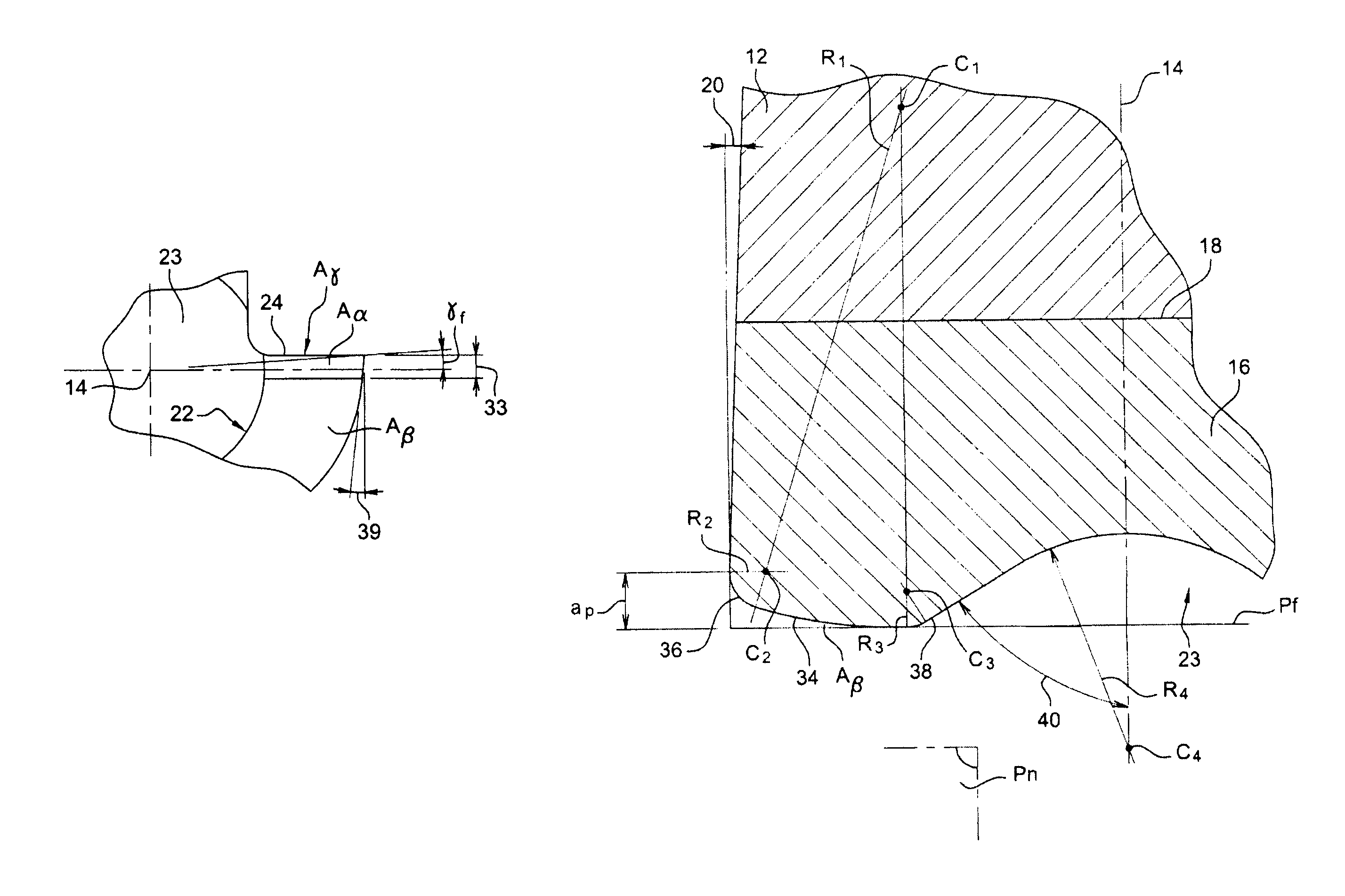
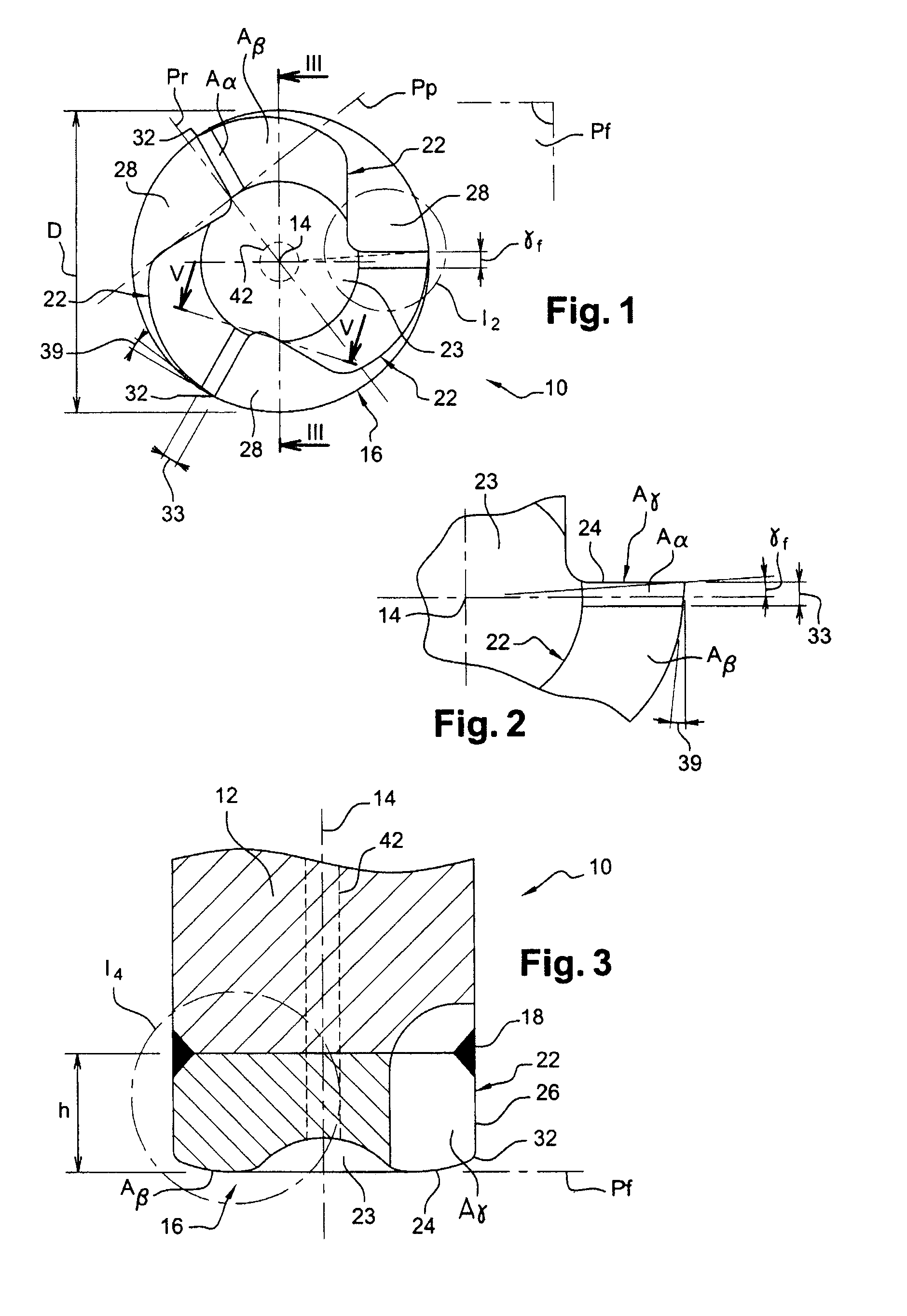
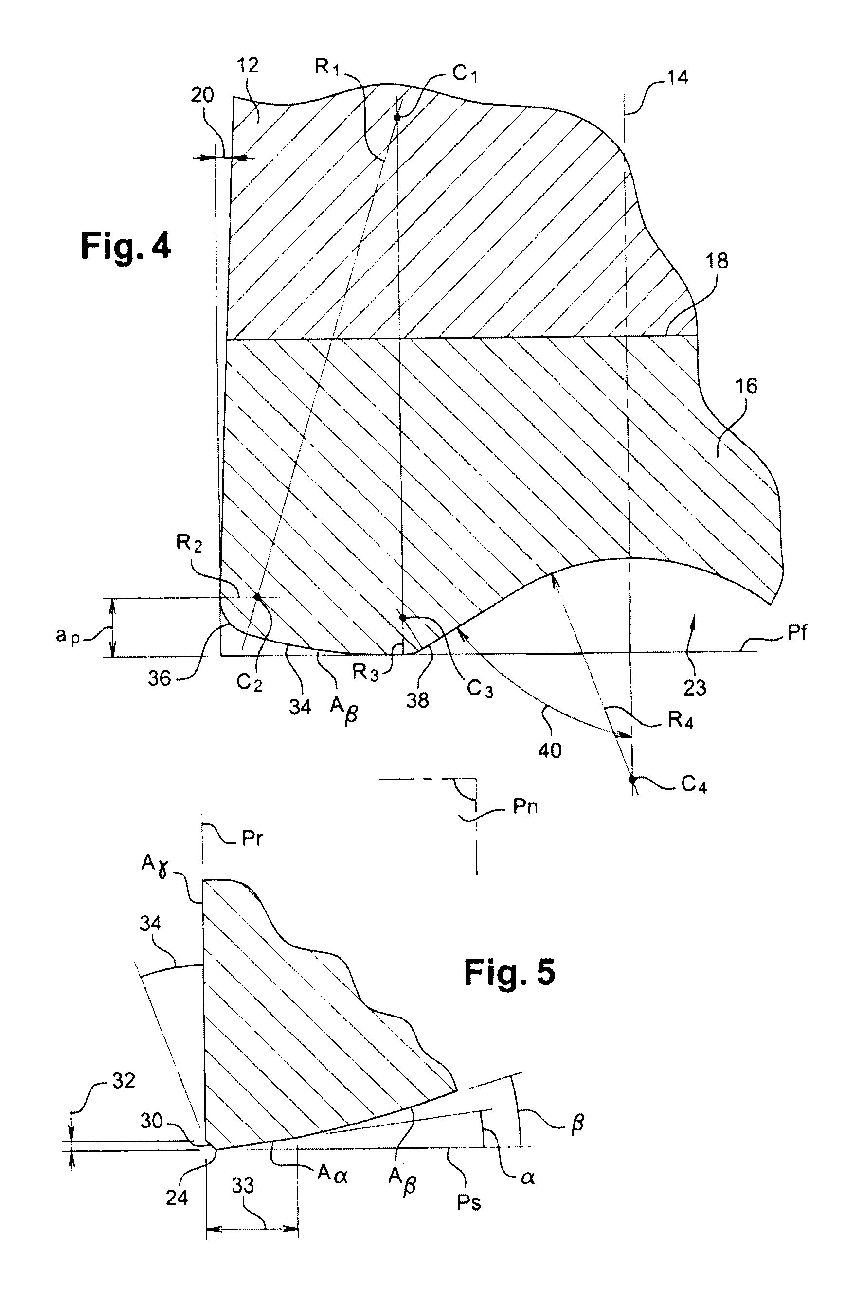
[0038]FIGS. 1 to 5 show a slotting milling cutter 10 according to the invention for machining at high speed and with a low pass depth of parts made of high-hardness materials, such as aeronautical materials made of a composite or a superalloy (for example Inconel 718).

[0039]This milling cutter 10 has a carbide body 12 of elongate shape extending along the rotation axis 14 of the milling cutter and, fixed to a free end of this body by brazing, is a head 16 cut from a ceramic, forming the active part of the milling cutter. To give an example, the body 12 of the milling cutter is made of tungsten carbide and its head 16 is made of an alumina-based ceramic. The brazed joint 18 lies in a plane perpendicular to the rotation axis 14 of the milling cutter (FIG. 3). The body 12 of the milling cutter is intended to be fixed by suitable means to the mandrel of a machine tool.

[0040]The milling cutter 10 has a general shape of a truncated cone. The large base of the truncated cone is located lev...


PUM

PropertyMeasurementUnit
angleaaaaaaaaaa
angleaaaaaaaaaa
radial cutting angleaaaaaaaaaa

Abstract

Slotting milling cutter, comprising a carbide body (12) and a ceramic head (16) fixed by brazing to one end of the body, this head having teeth (22), each comprising a cutting edge (24) formed by the intersection between a front cutting face (Aγ) and a lower flank face, in which the milling cutter has a frustoconical general shape, the profile of the flank face, formed by the intersection of the flank face with a plane passing through the axis of the milling cutter, has an outwardly convex rounded shape, and the radial cutting angle is negative.

Description

BACKGROUND OF THE INVENTION[0001]The present invention relates to a milling cutter, in particular to a slotting milling cutter, for machining with a high feed and a low pass depth, this milling cutter being particularly, but not exclusively, suitable for machining parts made of very hard materials used in the aeronautical industry.[0002]An aircraft turbomachine comprises, for example, many parts made of high-hardness materials such as composites and superalloys based on nickel and cobalt. The high-speed machining of these materials generates high thermal and mechanical stresses in the cutting tools, which therefore have to be made of materials that are very strong and resistant to high temperatures.[0003]It is known to manufacture a slotting milling cutter from a block of a ceramic or carbide material. A ceramic milling cutter has a high hardness and a high thermal resistance, and makes it possible for high-speed machining and high rates of material removal to be achieved. However, ...

Claims


Application Information

Patent Timeline
Patent Type & Authority Patents(United States)
IPC IPC(8): B23C5/10B23C5/14
CPCB23C5/10Y10T407/1948B23C2210/0435B23C2210/084B23C2215/04B23C2220/36B23C2222/28B23C2222/64B23C2226/18B23C2240/08B23C2265/08Y10T407/1966Y10T407/1928Y10T409/303808Y10T407/1924B23C2210/0421B23C5/1018
Inventor ROUGE, GILLESTHOISON, PASCAL CHARLES EMILETURRINI, CLAUDE ROGER ROBERT
Owner SN DETUDE & DE CONSTR DE MOTEURS DAVIATION S N E C M A
Why Eureka
Try Eureka