
Cooling apparatus having a variable speed compressor with speed limited on the basis of a sensed performance parameter

a technology of variable speed compressor and performance parameter, which is applied in the direction of domestic cooling apparatus, lighting and heating apparatus, refrigeration components, etc., can solve the problems of increasing the production cost of motor and power supply circuit, the uniform upper limit of the rotating speed of the motor, and the inability of the cooling apparatus to deliver the original full cooling capacity, etc., to achieve the effect of preventing the rotation speed of the motor, reducing the production cost of the motor and providing the uniform upper limit of the rotating speed of th

Inactive Publication Date: 2012-03-20
HOSHIZAKI ELECTRIC CO LTD
View PDF15 Cites 10 Cited by
  • Summary
  • Abstract
  • Description
  • Claims
  • Application Information

AI Technical Summary

Benefits of technology

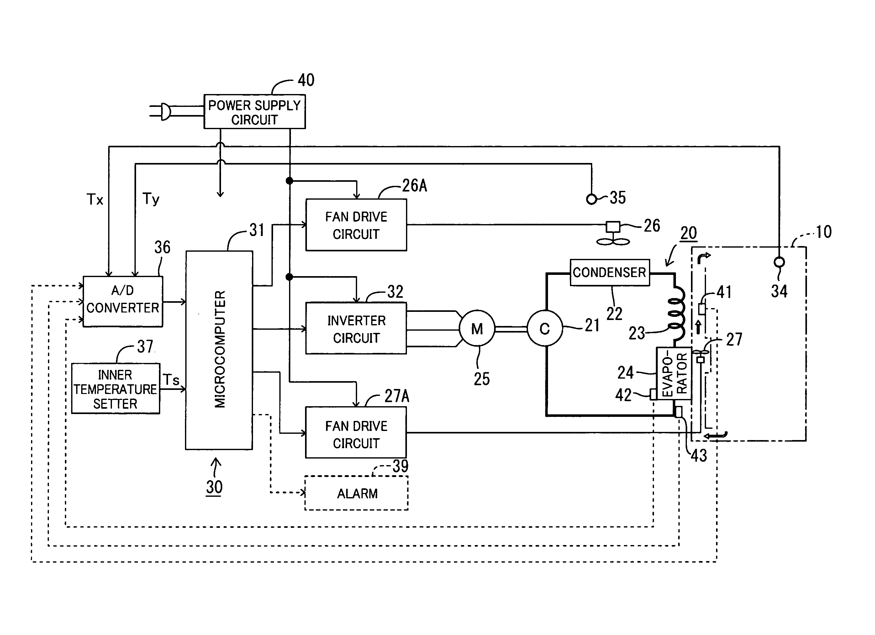
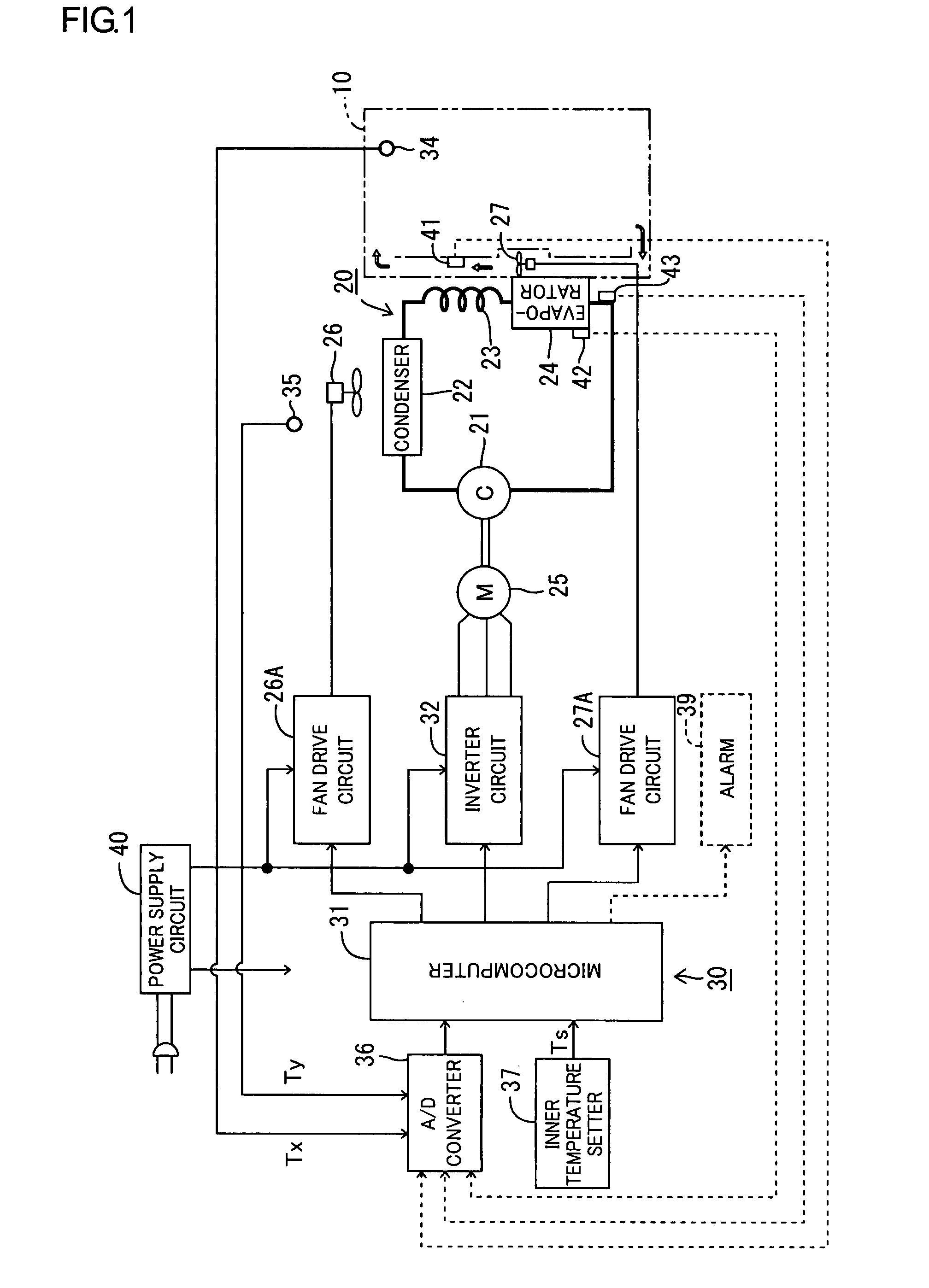
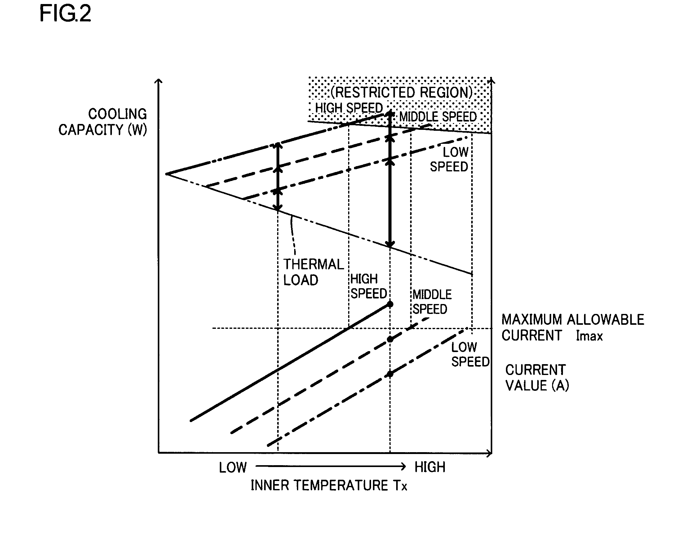
[0014]Thus, according to the present invention, the upper limit of the rotating speed of the motor is determined according the performance margin of the refrigeration cycle. Accordingly, the upper limit of the rotating speed of the motor is increased when the performance margin of the refrigeration cycle is sufficiently high, for example, when the temperature in the room where the cooling apparatus is installed is low. Consequently, the refrigeration cycle performs to the best of its potential, whereby quick cooling can be realized. Additionally, since the upper limit of the rotating speed is set, the rotating speed of the motor can be prevented from being increased more than is necessary even when the temperature of the object to be cooled is high. Thus, the capacity of the motor and accordingly the capacity of the power supply circuit therefor can be suppressed to smaller values.

Problems solved by technology

As a result, production costs of the motor and power supply circuit are increased.
However, the rotating speed of the motor is provided with a uniform upper limit in the conventional control manner.
Despite this, there is a case where the rotating speed of the motor reaches an upper limit thereof such that the cooling apparatus cannot deliver its original full cooling capacity.
In this case, a useless rotating speed limit is rendered effective so that a time period required to reach a set temperature is prolonged.
This means that the refrigerating capacity cannot be utilized effectively.
In the case where the foregoing temperature control is carried out when the temperature of the object differs from a target temperature to a large degree such as in the starting of the cooling apparatus, there is a possibility that an increased motor speed may result in occurrence of a large current.
Accordingly, the upper limit of the rotating speed of the motor is increased when the performance margin of the refrigeration cycle is sufficiently high, for example, when the temperature in the room where the cooling apparatus is installed is low.

Method used


Image

  • Cooling apparatus having a variable speed compressor with speed limited on the basis of a sensed performance parameter
  • Cooling apparatus having a variable speed compressor with speed limited on the basis of a sensed performance parameter
  • Cooling apparatus having a variable speed compressor with speed limited on the basis of a sensed performance parameter

Examples


first embodiment

[0040]Furthermore, in the first embodiment, the refrigeration cycle 20 is controlled in a steady operation after the start so that the rotating speed of the motor 25 is rendered higher as the temperature gradient of the inner temperature Tx is increased, namely, the cooling capacity of the refrigeration cycle 20 is rendered higher. Accordingly, the inner temperature Tx sometimes changes suddenly from the set temperature Ts under the steady operation of the refrigerator when one or more articles to be cooled are newly put into the storage compartment, when articles which have already been cooled are taken out of the storage compartment, or the like. In this case, the compressor 21 is operated at high speeds so that the cooling capacity is rendered higher, whereby a temperature increase in the storage compartment is corrected quickly and accurately, and the inner temperature Tx is maintained substantially at the set temperature Ts in the steady operation of the refrigeration cycle.

[00...

second embodiment

[0043]The upper limit rotating speed is determined in the following manner in the More specifically, the microcomputer 31 determines at step S24 whether or not the inner temperature Tx is at or above 13° C. or whether or not the condenser temperature is at or above 63° C. When determining in the affirmative (Yes), the microcomputer 31 then determines whether or not the current rotating speed of the motor 25 is at or above 65 rps. The determination at step S25 actually depends upon the value of frequency command signal the microcomputer 31 supplies to the inverter circuit 32. When the rotating speed is at or above 65 rps, the microcomputer 31 maintains the rotating speed or reduces the rotating speed to 65 rps (step S26). Furthermore, when determining in the negative (No) at step S24 or S25 and the rotating speed is set to 65 rps at step S26, the microcomputer 31 advances to step S27 to determine whether or not the inner temperature is at or above 20° C. or whether or not the conden...

third embodiment

[0049]The upper limit rotating speed is determined in the following manner in the More specifically, the microcomputer 31 determines at step S34 whether or not the inner temperature Tx is at or above 13° C. or whether or not the refrigerant pressure is at or above 1.8 MPa. When determining in the affirmative (Yes), the microcomputer 31 then determines whether or not the current rotating speed of the motor 25 is at or above 65 rps. The determination at step S35 actually depends upon the value of frequency command signal the microcomputer 31 supplies to the inverter circuit 32. When the rotating speed is at or above 65 rps, the microcomputer 31 maintains the rotating speed or reduces the rotating speed to 65 rps (step S36). Furthermore, when determining in the negative (No) at step S34 or S35 and when the rotating speed is set to 65 rps at step S36, the microcomputer 31 advances to step S37 to determine whether or not the inner temperature is at or above 20° C. or whether or not the ...


PUM


Abstract

A cooling apparatus such as a refrigerator includes a refrigeration cycle including a compressor driven by an electric motor, a condenser, a throttle valve and an evaporator, a first physical amount detector capable of detecting a physical quantity representing a temperature of an object to be cooled by the cooling operation of the evaporator, a temperature control device capable of controlling a rotating speed of the motor based on the physical quantity detected by the first physical quantity detector so that the object is cooled approximately to a target temperature, a second physical quantity detector capable of detecting a physical quantity corresponding to a performance margin of the refrigeration cycle, and a rotating speed limiter capable of limiting the rotating speed of the motor to or below a predetermined speed based on a physical quantity detected by the second physical quantity detector.

Description

BACKGROUND[0001]I. Technical Field[0002]The present invention relates to a cooling apparatus, more specifically a compressor of a refrigeration cycle driven by an electric motor of the speed control type.[0003]II. Description of the Related Art[0004]JP-H11-173729A and JP-S60-188775A disclose cooling apparatuses of refrigerators. It is known that an inner temperature, which is a temperature inside a cooling apparatus, is detected and a rotating speed of the electric motor is controlled using the detected inner temperature. In this technique, the rotating speed of the motor is controlled so as to be increased as the inner temperature rises, exceeding a set temperature, for example, about 5° C., so that a cooling capacity of the refrigeration cycle is increased, whereupon the inner temperature is kept substantially equal to the set temperature.[0005]In the above-described conventional cooling apparatuses, however, when the inner temperature which is close to a room temperature (which i...

Claims


Application Information

Patent Timeline
Patent Type & Authority Patents(United States)
IPC IPC(8): F25B1/00F25B49/00
CPCF25B49/02F25B2600/021F25B2600/111F25B2600/112F25B2700/197F25B2700/2104F25B2700/2116Y02B30/741Y02B30/743Y02B30/70
Inventor KAGA, SHINICHIUEDA, TAKESHISUZUKI, YOSHIYASUHIRANO, AKIHIKO
Owner HOSHIZAKI ELECTRIC CO LTD
Learn More