Mixer circuit and method of operation

a mixer circuit and mixer technology, applied in the field of mixer circuits, can solve the problems of single-balanced mixer circuits that do not properly reject lo signals or harmonics, and the second order intermodulation distortion (im2) presents an undesired spectral component, so as to reduce the power consumption of mixer circuits

Inactive Publication Date: 2012-03-20
ST ERICSSON SA
View PDF7 Cites 28 Cited by
  • Summary
  • Abstract
  • Description
  • Claims
  • Application Information

AI Technical Summary

Benefits of technology

[0016]In the above mixer the use of chopping switches increases the IIP2. Furthermore, the dummy branch prevents the LO signal from passing to the IF signal. Thus, the above mixer circuit achieves a better noise rejection that the embodiment of FIG. 8 of EP 1 111 772 while still achieving equivalent or better IIP2.
[0025]The above embodiments of the mixer circuit present the following advantages:
[0026]cross-switching the connection of the transconductance stage of the mixing and dummy branches with the current switching core of the mixing and dummy branches improves the rejection of the LO signal in the generated IF signal,
[0029]using a filter having a cut-off frequency strictly higher than zero allows for cancellation of IM2 produced by the chopping switches, and
[0030]having the transconductance stage directly connected to a DC current source without passing through one of the current switching stages, decreases the power consumption of the mixer circuit.

Problems solved by technology

Because of limited narrow band selectivity, second order intermodulation distortion (IM2) presents an undesired spectral component within the signal band of interest.
In reality, this is far from the truth; due, in no small part, to device mismatches, parametric imbalance, imperfect layout, and other device characteristic inequalities that cause imbalances and provides a lower than desired second order input intercept point (IIP2).
However, this single-balanced mixer circuit does not properly reject the LO signal or harmonic of the LO signal in the IF signal.

Method used


Image

  • Mixer circuit and method of operation
  • Mixer circuit and method of operation
  • Mixer circuit and method of operation

Examples


Embodiment Construction

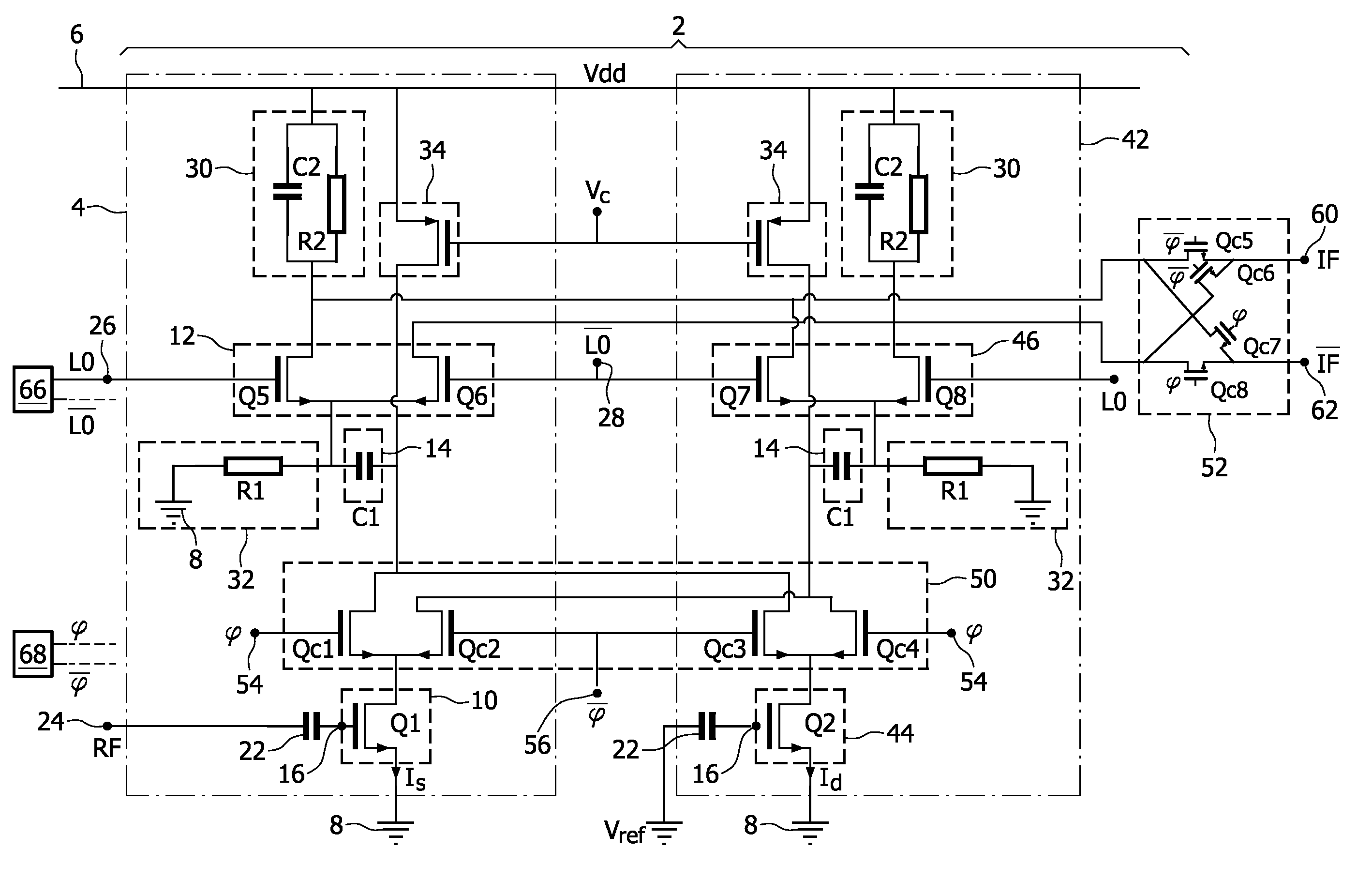
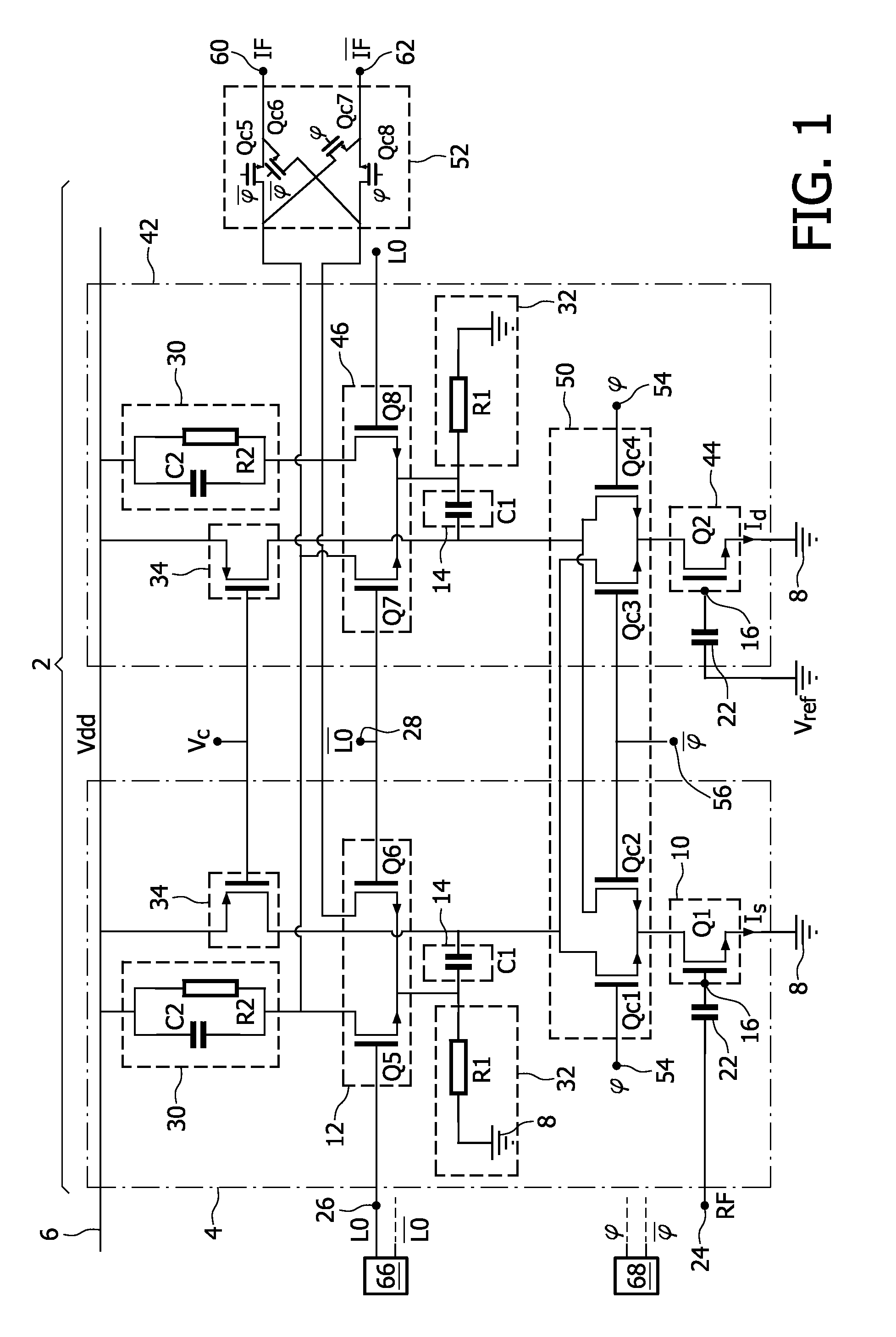
[0037]FIG. 1 shows a mixer circuit 2 which is intended to mix LO signal with an RF signal to obtain the IF signal.

[0038]To this end, circuit 2 has a mixing branch 4 connected between a DC supply line 6 and a reference potential 8 like ground.

[0039]Branch 4 has a transconductance stage 10 which is connected to a current switching core 12 through a filter 14.

[0040]Stage 10 is able to transform the RF signal received on an input 16 into a current signal Is. For example, stage 10 includes a transistor Q1 having a base connected to an input 16, an emitter connected to ground 8 and a collector connected to core 12 though filter 14.

[0041]Input 16 is connected to a RF input 24 through a capacitor 22.

[0042]Current switching core 12 is designed to switch current Is according to the LO signal.

[0043]For example, core 12 includes two transistors Q5 and Q6, emitters of which are connected together. The base of transistors Q5 and Q6 are directly connected to an LO input 26 and a LO input 28, respe...


PUM


Abstract

A mixer circuit to mix a RF (Radio Frequency) signal with a LO (Local Oscillator) signal to generate an IF (Intermediate Frequency) signal including a dummy branch connected in parallel of a mixing branch, the dummy branch including a transconductance stage having an input connected to a reference potential independent from the RF signal, to transform the reference potential into a current signal, and a current switching core to switch the current signal according to LO and signals, and chopping switches to connect in series the transconductance stage of the mixing branch to the current switching core of the mixing branch and, in the alternative, to the current switching core of the dummy branch under the control of a chopping signal.

Description

CROSS-REFERENCE TO RELATED APPLICATIONS[0001]The present application is a national filing in the U.S. Patent & Trademark Office of PCT / IB2007 / 052298 filed Jun. 15, 2007, and claims priority of EPO Patent Application No. 06300726.4 filed Jun. 27, 2006, both of which applications are incorporated herein in their entireties by this reference.FIELD OF THE INVENTION[0002]The present invention relates to a mixer circuit and a method to operate this mixer circuit.BACKGROUND OF THE INVENTION[0003]In direct conversion and zero-IF (Intermediate Frequency) receivers, it is necessary to maintain the spectral purity of the channel used for reception. Because of limited narrow band selectivity, second order intermodulation distortion (IM2) presents an undesired spectral component within the signal band of interest. This occurs when two or more interfering signals, whose difference in frequency is less than the IF bandwidth of the desired signal, mix with one another due to some second order nonli...

Claims


Application Information

Patent Timeline
Patent Type & Authority Patents(United States)
IPC IPC(8): H04B1/26
CPCG06F7/58H03D7/1441H03K3/84H03D7/1458H03D7/1475H03D7/1483G06F7/584G06F2207/581G06F2207/583
Inventor VILLAIN, FREDERIC F.BURG, OLIVIER
Owner ST ERICSSON SA
Why Eureka
Try Eureka