
Sensor unit for a surface plasmon resonance (SPR) unit

a surface plasmon and sensor technology, applied in the field of surface plasmon resonance (spr) sensors, can solve the problems of high cost, wear, and wear of opto-gels, and achieve the effect of convenient and inexpensive manufacturing

Active Publication Date: 2012-04-03
JOHANSEN KNUT
View PDF16 Cites 8 Cited by
  • Summary
  • Abstract
  • Description
  • Claims
  • Application Information

AI Technical Summary

Benefits of technology

The device simplifies the analysis of multiple samples by eliminating the need for refractive index matching media and complex optics, reducing costs and maintenance, while enabling precise temperature control and efficient mass transport, making it suitable for biosensing and gas sensing applications.

Problems solved by technology

The surface plasmon will reradiate into the prism, and for a certain thickness of the plasma a destructive interference will occur, leading to zero or close to zero intensity of the reflected light.
The use of an opto-gel has the disadvantage of wear, optical imperfection and high cost.
If a refractive index matching fluid is used, a circumstantial procedure of application and cleaning is needed, besides the extra cost.
Using a planar sensor surface with multiple sensor areas arranged in a two-dimensional way, means that there are a couple of somewhat cumbersome (and expensive) ways to read the optical output from the surface plasmon resonance device.
Not only is the read out complex, but the distribution of samples for investigation is often very complex, with use of valves and channels or expensive autosamplers.
However, there are approaches that do not use planar substrates.
It can, with difficulties be used as an axial multispot sensor, and with severe difficulties may be with some sensors spots radially separated.
However, this approach has several disadvantages.
It is very difficult to cover the inside of the capillary tube with a metal of precise thickness, due to the small diameter and long length.
Capillary tubes are not normally high precision optics, which will distort optical images.
The capillary device is suitable for one or a few sensing spots, and the small diameter means that there will be difficulties to manufacture device with many sensors spots.
The capillary device has typically a relatively large diameter, e.g. 400 μm, compared to a thin flowcell, e.g. 10 μm, making the capillary tube inefficient regarding small sample volumes, and mass transport.
Using a small radius at the surface plasmon carrying surface, will not only lead to mismatch between wavevector for surface plasmon and incident light, but also leads to difficulties to obtain small light beams and smooth reflectance curves.

Method used


Image

  • Sensor unit for a surface plasmon resonance (SPR) unit
  • Sensor unit for a surface plasmon resonance (SPR) unit
  • Sensor unit for a surface plasmon resonance (SPR) unit

Examples


example 1

Experiments

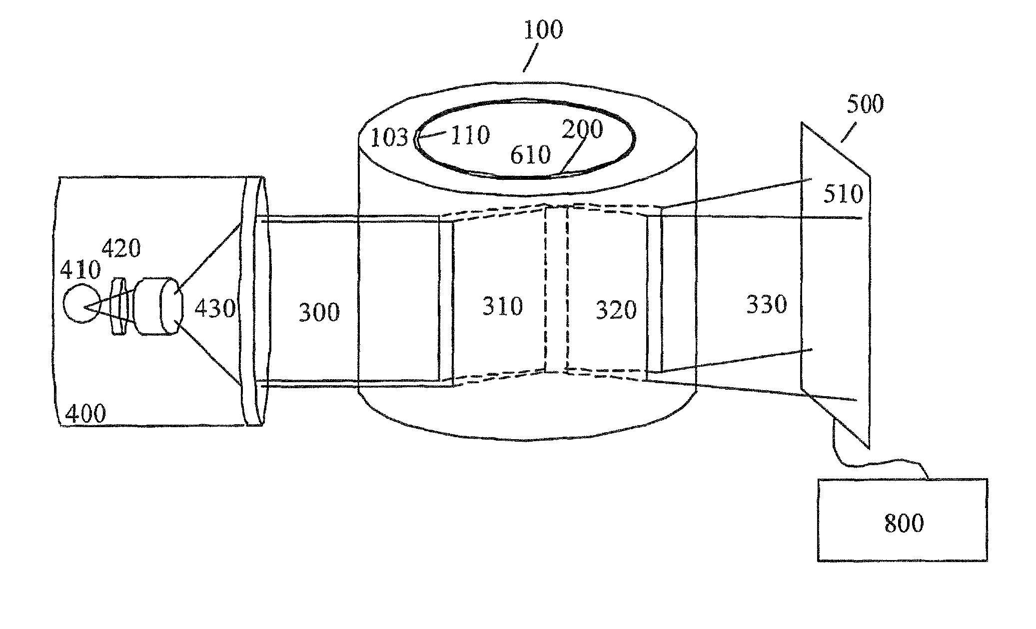
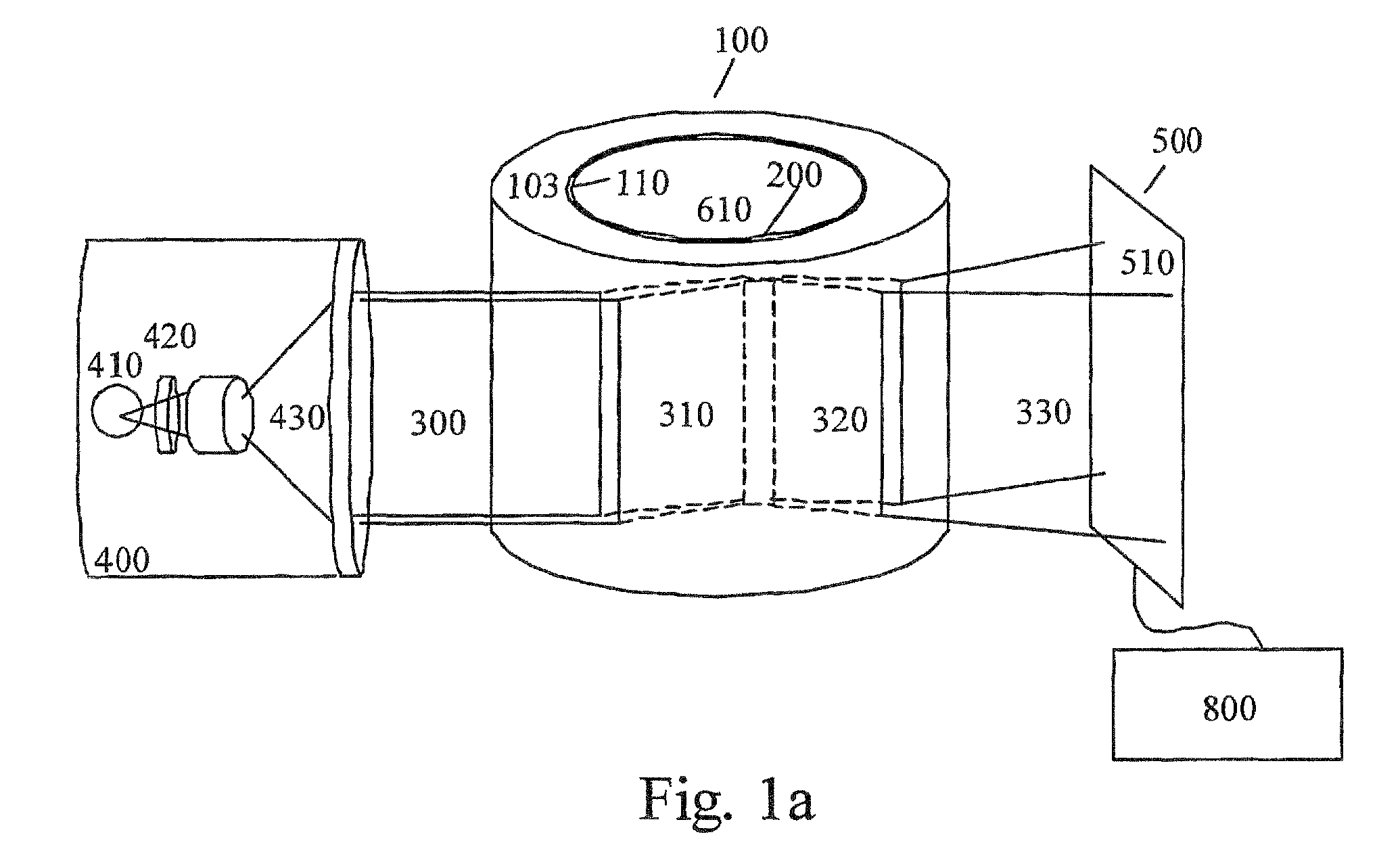
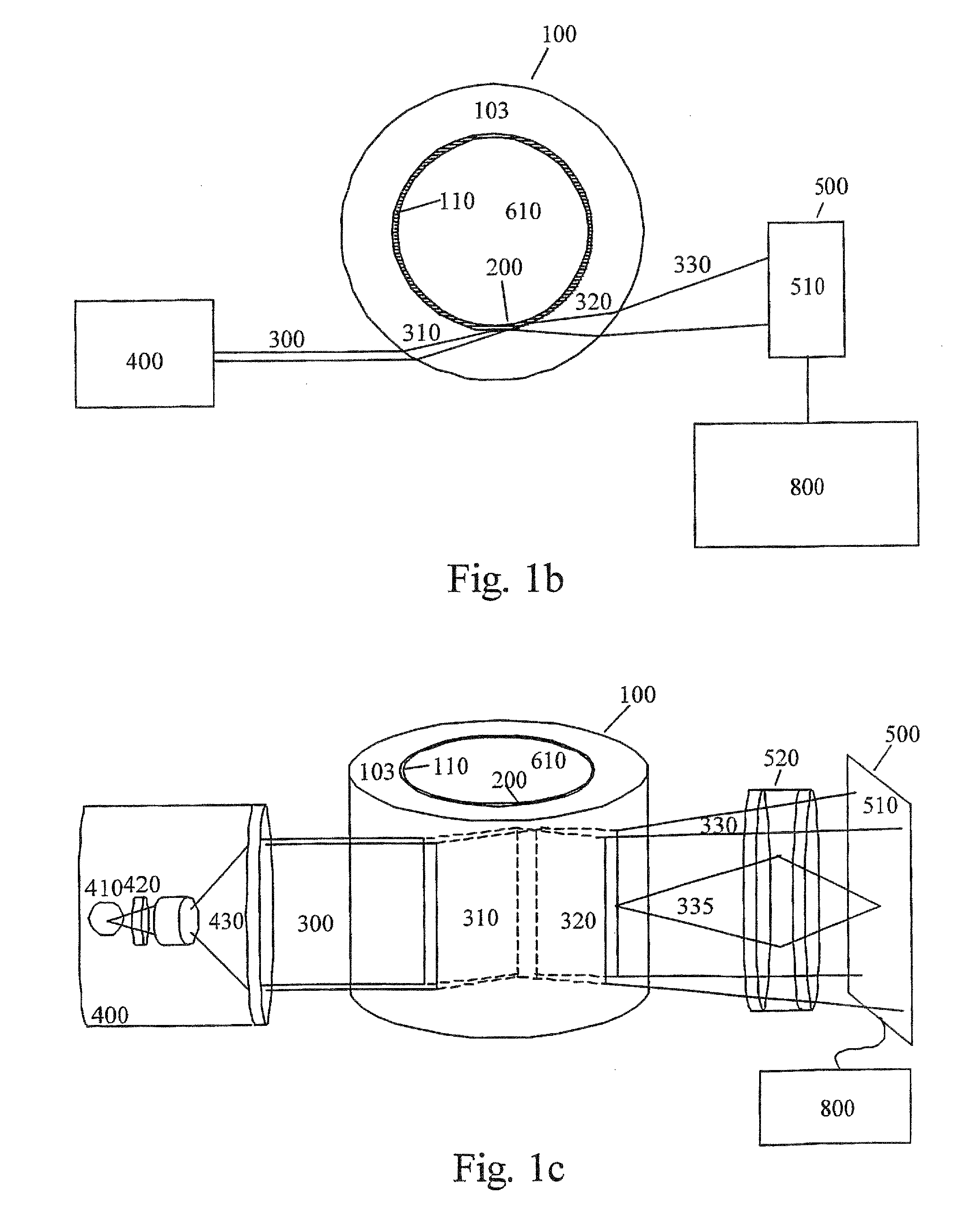
[0151]FIG. 22a, illustrates the signal from the detector 500, seen on the computer 800 from one embodiment of the surface plasmon resonance apparatus of the invention as illustrated in FIG. 3a-b. The embodiment utilizes a monochromatic light source comprising a 5 mW HeNe laser (Melles-Griot) 400, emitting coherent and p-polarized (with respect to the sensor surface) light 300 at a wavelength of 633 nm. The light 300 impinges on the outer surface of the substrate 103 made of Duran (Schott) glass with a refractive index of 1.5, and with outer and inner diameters of 15 mm and 10 mm respectively. The glass substrate is sputtered with approximately 0.5 nm chromium acting as the adhesion layer 105 for the surface plasmon supporting metal layer 110. The surface plasmon supporting metal layer 110 is sputtered to a thickness of 50 nm. Both metal layers 105 and 110 are deposited using physical vapor deposition techniques (PVD). Sample 200 consists of sucrose solutions ranging from ...


PUM

PropertyMeasurementUnit
diameteraaaaaaaaaa
diameteraaaaaaaaaa
diameteraaaaaaaaaa

Abstract

The invention relates to a sensor unit for a Surface Plasmon Resonance (SPR) unit, comprising a transparent sensor structure forming at least one wall of a cavity, the wall being defined by a concave inner surface and a convex outer surface The inner surface is provided with a layer of a conductive material capable of supporting a surface plasmon. In the cavity there is provided a flow structure in said cavity so as to form at least one compartment for sample between the flow structure and the inner wall of the cavity. Also, a method for the detection of events at a surface by utilizing surface plasmon resonance is provided. It comprises placing a sample with an analyte of interest in a sensor unit as claimed in claim 1, and measuring the reflectance from said sensor unit at a single or plurality of angle / angles.

Description

[0001]This application is a U.S. National Phase Application under 35 USC 371 of International Application PCT / SE2007 / 000950 filed Oct. 29, 2007, which claims priority from Swedish Application No. SE 0602286-7 filed Oct. 31, 2007, the entire disclosure of each of which is incorporated herein by reference.FIELD OF THE INVENTION[0002]The present invention relates to a method, apparatus and device for optical surface analysis of a plurality of sample areas on a curved sensor unit using surface plasmon resonance. The invention is particularly concerned with a rotational symmetric container or tube or a device using an angular part of a rotational symmetric container, using surface plasmon resonance (SPR), suitable for use in biological, biochemical, chemical and physical analyzing, as well as gas sensing, where the container or tube may be fixed or movable, e.g. rotating or oscillating.BACKGROUND OF THE INVENTION[0003]There is an interest in surface sensitive techniques for analyzing the...

Claims


Application Information

Patent Timeline
Patent Type & Authority Patents(United States)
IPC IPC(8): G01N21/55G01J4/00
CPCG01N21/553G01N21/03G01N2021/0346G01N2021/0307G01N33/543
Inventor JOHANSEN, KNUTRANBY, MATS
Owner JOHANSEN KNUT
Learn More