Pressure boosting system for at least one fuel injector

a technology of fuel injector and pressure booster, which is applied in the direction of positive displacement liquid engine, pump, machine/engine, etc., can solve the problems of large control quantity to be diverted, relative large control quantity for triggering the pressure booster, adversely affecting the hydraulic efficiency of such fuel injection system, etc., and achieve the effect of increasing the efficiency of the pressure booster of the fuel injection system

Inactive Publication Date: 2012-04-24
ROBERT BOSCH GMBH
View PDF17 Cites 5 Cited by
  • Summary
  • Abstract
  • Description
  • Claims
  • Application Information

AI Technical Summary

Benefits of technology

[0007]It is the object of the present invention to minimize the lost quantities that occur from leakage at guide gaps, in order to increase the efficiency of the pressure boosting of the fuel injection system.
[0008]The hydraulic pressure booster employed has a piston guide body, embodied on the base body, for at least one of the pressure booster piston parts, which part is at least partly surrounded by an annular chamber that in turn is part of the hydraulic reservoir chamber. Thus the same pressure prevails in the annular chamber as in the hydraulic reservoir chamber. Because of the surrounding annular chamber, particularly in the pressure boosting state, a supporting pressure exerted from outside is imparted to the piston guide body, as a result of which internal piston guides open less widely or are not widened as much. Consequently, the guide gaps are reduced, and the leakage quantity is minimized. Moreover, as a result, a component load, induced in the guide body, on the differential pressure between the reservoir volume and the high-pressure volume is reduced, so that the effort and expense for high-pressure-proof design and embodiment of the entire hydraulic pressure booster can be lowered. The pressure boosting system according to the invention is moreover optimized in terms of the installation space required for individual system components. Overall, a considerable increase in the total efficiency of the pressure boosting system is achieved.
[0012]It is especially advantageous that the pressure booster is provided centrally for a plurality of fuel injectors and is disposed between a high-pressure pump and a high-pressure reservoir. Because of a modular construction of the high-pressure pump, pressure booster, high-pressure reservoir, and fuel injector, this kind of central pressure booster can be used in all known installation spaces of internal combustion engines. Because of the disposition of the central hydraulic pressure booster between the high-pressure pump and the high-pressure reservoir (common rail), the central pressure booster has to be triggered only once per injection cycle of a fuel injector. As a result, the control quantity and the leakage quantity are reduced considerably, as a function of the number of injections. Because of this circumstance, the high-pressure pump can be embodied with smaller dimensions as well, since less fuel has to be supplied, because the number of refilling phases of the control chamber of the central hydraulic pressure booster is reduced considerably. The central pressure booster can as a result be designed in terms of its high-pressure supply quantity for the maximum possible injection quantity of at least one fuel injector.

Problems solved by technology

A disadvantage of the known pressure boosting system is the relatively large control quantity for triggering the pressure booster.
The result is a large control quantity to be diverted, which must accordingly be included in the lost quantity in the injection system.
Moreover, with increasing injection pressures, the lost quantity increases proportionally to the fourth power by way of the gap width in the guide of the pressure booster piston, which adversely affects the hydraulic efficiency of such fuel injection systems.

Method used


Image

  • Pressure boosting system for at least one fuel injector
  • Pressure boosting system for at least one fuel injector
  • Pressure boosting system for at least one fuel injector

Examples


Embodiment Construction

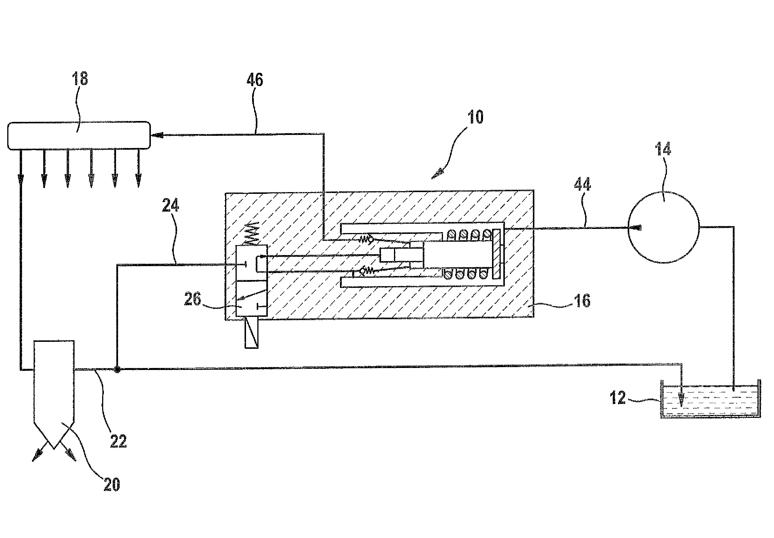
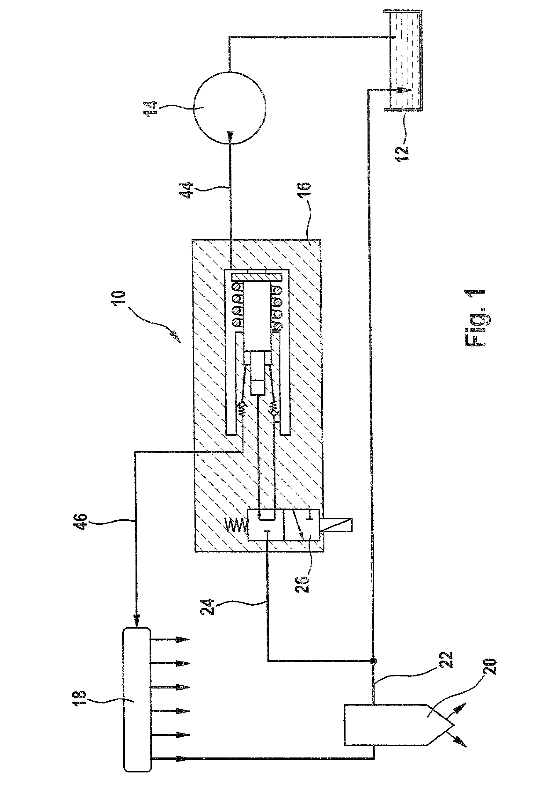
[0028]The fuel injection system shown in FIG. 1 has a modular construction of a high-pressure injection system 10, which can be applied for instance to all the installation spaces of internal combustion engines. The high-pressure injection system 10 includes a fuel tank 12, from which fuel is supplied via a high-pressure pump 14 and directed to a hydraulic pressure booster 16. On the one hand, the hydraulic pressure booster 16 communicates via a pressure booster inlet 44 with the aforementioned high-pressure pump 14, and on the other, it acts upon a high-pressure reservoir 18 (common rail). Connection lines, shown only schematically in FIG. 1 and corresponding in number to the number of fuel injectors to be supplied with fuel at system pressure, to fuel injectors 20 are located in the high-pressure reservoir 18. The central hydraulic pressure booster 16 thus in FIG. 1 supplies pressure-boosted fuel to all the fuel injectors 20. However, it is also conceivable for the hydraulic press...


PUM


Abstract

The invention relates to a pressure boosting system for at least one fuel injector of a high pressure injection system of an internal combustion engine, having a hydraulic pressure booster that is actuated by a control valve. The hydraulic pressure booster is configured with a pressure boosting piston, which comprises a first pressure booster piston part having a first diameter and a second pressure booster piston part having a second diameter, wherein the first diameter is greater than the second diameter. The pressure booster piston is disposed within a hydraulic reservoir chamber, onto which pressure is applied, together with the first pressure booster piston part having the greater diameter, wherein the accumulator chamber in turn is configured within a base body. The base body has a piston guide body for at least one of the pressure booster piston parts. The piston guide body is at least partially surrounded by an annular space, which is part of the hydraulic accumulator chamber.

Description

CROSS-REFERENCE TO RELATED APPLICATION[0001]This application is a 35 USC 371 application of PCT / EP2008 / 054531 filed on Apr. 15, 2008.BACKGROUND OF THE INVENTION[0002]1. Field of the Invention[0003]The invention relates to a pressure boosting system for at least one fuel injector of an internal combustion engine, having a hydraulic pressure booster.[0004]2. Description of the Prior Art[0005]A fuel injection system with pressure boosting, in which one central hydraulic pressure booster is provided for all the fuel injectors, is known from European Patent Disclosure EP 1 125 046 B1. The fuel supplied by means of a high-pressure pump is delivered to a central pressure reservoir (first common rail). The central pressure booster is downstream of the central pressure reservoir in the direction in which the fuel is supplied and carries the pressure-boosted fuel to a further pressure reservoir (second common rail), from which a plurality of pressure lines, corresponding in number to the numb...

Claims


Application Information

Patent Timeline
Patent Type & Authority Patents(United States)
IPC IPC(8): F02M57/02F02M37/00
CPCF02M59/105F02M63/027F02M57/026
Inventor KUHNKE, DOMINIKVAHLE, DIRK
Owner ROBERT BOSCH GMBH
Why Eureka
Try Eureka