In-chamber electron detector

a detector and chamber technology, applied in the field of particle detectors, can solve the problems of significant light loss, limited flexibility of dual beam system users, and loss of light, and achieve the effect of eliminating a source of signal loss and strong secondary electron signal

Active Publication Date: 2012-04-24
FEI CO
View PDF31 Cites 3 Cited by
  • Summary
  • Abstract
  • Description
  • Claims
  • Application Information

AI Technical Summary

Benefits of technology

[0018]This invention provides an improved detector using a scintillator and a transducer, such as photomultiplier tube, a photodiode or a phototransistor, in which the transducer, as well as the scintillator, is positioned entirely within the sample vacuum chamber. The transducer converts the light from the scintillator to an electrical signal. By positioning the transducer within the vacuum chamber, the designer is not constrained in positioning the scintillator by a light pipe that is required in the prior art to lead the light from the vacuum chamber, and the detector can be positioned to provide a stronger secondary electron signal that prior art detectors. Eliminating the optical components required to lead the light out of the vacuum chamber eliminates a source of signal loss.

Problems solved by technology

Thus, users of dual beam systems have limited flexibility in adapting their systems for new accessories and new applications.
Moreover, at each interface in the light path, some of the light is lost.
Conducting the light to the window, through the window, and then into the PM tube results in significant loss of light.
The surface also is prone to degradation when the chamber is vented for sample exchange.
Thus, CDEMs are not efficient in many applications, in which many chemicals are used.
Thus, the CDEM is typically placed in a good position for signal collection, but has limited lifetime.
The ETD has good lifetime but is mounted in the wrong place for good signal collection and loses signal as the light moves through coupled components to outside the vacuum chamber.
The inflexibility of positioning the ETD makes it difficult to reconfigure the instrument to move other devices close to the sample for particular applications.
The market need for both flexibility and long life have been known, but was not solved.

Method used


Image

  • In-chamber electron detector
  • In-chamber electron detector
  • In-chamber electron detector

Examples


Embodiment Construction

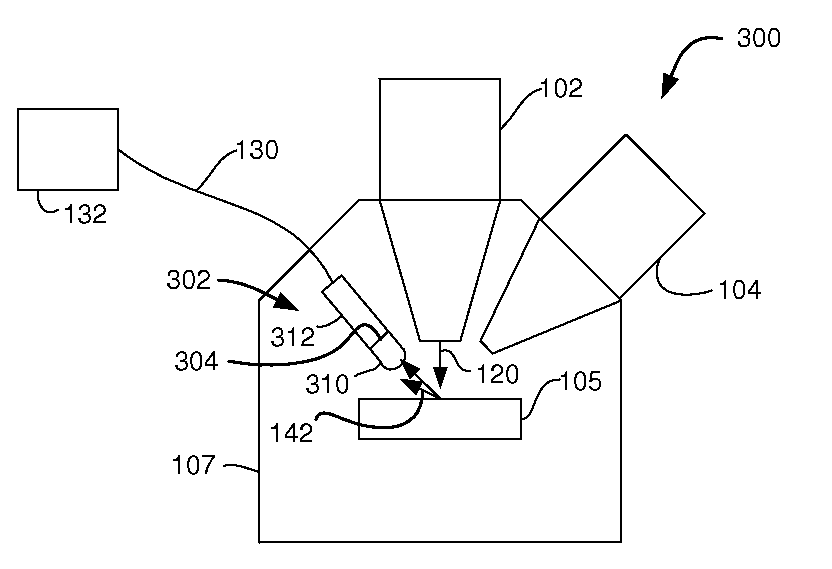
[0036]FIG. 3 shows a dual beam system 300 using an in-chamber ET (ICE) detector 302. Detector 302 includes a scintillator 304, typically of a phosphor material, and a transducer such as a compact photomultiplier tube 312, and a conductive grid 310 for attracting charged particles. A suitable compact photomultiplier tube is available, for example, from Hamamatsu Photonic KK, Shizuoka-ken, Japan. The photomultiplier tube is preferably less than 115 mm long, more preferably less than 75 mm, and even more preferably less than 55 mm long, and most preferably less than or about 30 mm long. An electrical lead 130 conducts the output of PM tube 312 to imaging circuitry 132 outside of the vacuum chamber 107. Because the PM tube 312 is within the vacuum chamber, no light tube is required to lead the light to a PM located positioned outside of the vacuum chamber.

[0037]It is noted that instead of a PM tube, other types of photon-to-current converters can be used, such as photodiodes or phototra...


PUM


Abstract

A secondary particle detector 302 for a charged particle beam system 300 includes a scintillator 304 and a transducer 312, such as a photomultiplier tube, positioned within a vacuum chamber 107. Unlike prior art Everhart-Thornley detectors, the photomultiplier is positioned within the vacuum chamber, which improves detection by eliminating optical couplings and provides flexibility in positioning the detector.

Description

TECHNICAL FIELD OF THE INVENTION[0001]The present invention relates to particle detectors for charged particle beam systems.BACKGROUND OF THE INVENTION[0002]Charged particles beam systems, such as electron beam systems and ion beam systems, can form images by detecting secondary or backscattered electrons or ions that are emitted when the primary beam impacts the work piece surface. For many years, scanning electron microscopes and focused ion beam systems have used a scintillator-photomultiplier detector, known as an Everhart-Thornley detector or simply an “ET detector,” or ETD to detect secondary electrons. Other types of electron detectors include a channel detection electron multiplier, (sometimes referred to as a continuous dynode electron multiplier or CDEM) and a multichannel plate (MCP).[0003]FIG. 1A shows schematically a typical prior art dual beam system 100 having an electron column 102 and a focused ion beam column 104 for operating on a sample 105 in a vacuum chamber 10...

Claims


Application Information

Patent Timeline
Patent Type & Authority Patents(United States)
IPC IPC(8): H01J37/244H01J37/256H01J37/28
CPCH01J37/244H01J37/28H01J2237/2443H01J2237/24435H01J2237/2445H01J2237/2448H01J2237/26
Inventor GERLACH, ROBERTMAAZOUZ, MOSTAFADINGLE, TREVORUTLAUT, MARKMCGINN, JAMES
Owner FEI CO
Why Eureka
Try Eureka