Method and system for generating power from a heat source

a technology of heat source and heat source, which is applied in the direction of indirect heat exchangers, machines/engines, lighting and heating apparatus, etc., can solve the problems of reducing efficiency, large temperature mismatches between working fluids, and limited condensing direct steam cycles, etc., and achieve the effect of reducing the temperatur

Active Publication Date: 2012-05-01
GRANITE POWER LTD
View PDF20 Cites 50 Cited by
  • Summary
  • Abstract
  • Description
  • Claims
  • Application Information

AI Technical Summary

Benefits of technology

[0012]expanding said superheated working fluid to drive a turbine, thereby reducing its temperature;
[0020]a turbine fluidly connectable to said first heat exchanger for expanding said superheated working fluid, thereby reducing its temperature;
[0026]Preferably, the method further includes the step of monitoring the temperature in said heat regenerating step. Preferably, the heat regenerating step includes controlling the pressure of at least one of the working fluid passing between the compressing step and the heat exchanging step and the working fluid passing between the expanding step and the condensing step, in response to said temperature monitoring step, thereby controlling the temperature of said at least one working fluid.

Problems solved by technology

Condensing direct steam cycles are limited to dry-steam geothermal reservoirs, which are much rarer than other geothermal reservoirs, such as hot-water and hot-dry-rock reservoirs.
In the context of geothermal sources, this results in large temperature mismatches between the working fluid and the geothermal heat source during the heat addition or the rejection processes in the thermodynamic cycle.
For example, in a binary cycle, the temperature difference between the working and geothermal fluids in the primary heat exchanger could be as high as 80° C. to 100° C. In terms of thermodynamics, larger temperature differences in the heat exchange process increase the entropy in the power cycle, thereby reducing the efficiency, particularly the second law efficiencies related to exergy (availability), of the heat exchange process and resulting in poor energy recovery for power generation.
A disadvantage of the Kalina cycle is that the absorption and distillation equipment added to the cycle creates further complexity to the system, and significantly increases the cost of plant installation compared with other types of power plants.
Furthermore, the Kalina cycle has a high sensitivity towards the pressure and composition of the ammonia-water mixture, which limits the operation of the cycle over the whole range of possible geothermal reservoir temperatures and effectively sets a lower limit to the minimum temperature at which a deep geothermal energy source may be commercialised.

Method used


Image

  • Method and system for generating power from a heat source
  • Method and system for generating power from a heat source
  • Method and system for generating power from a heat source

Examples


Embodiment Construction

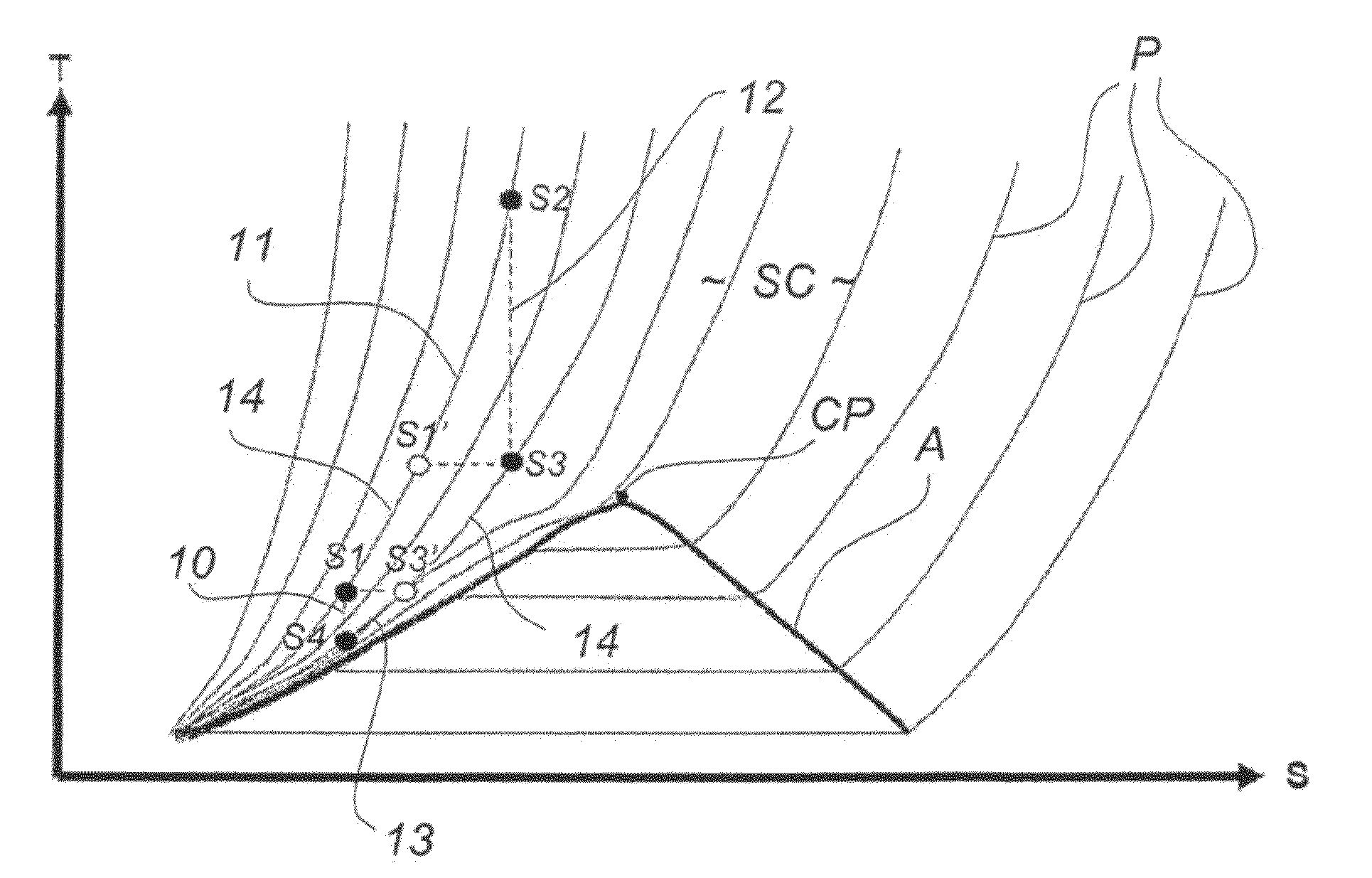
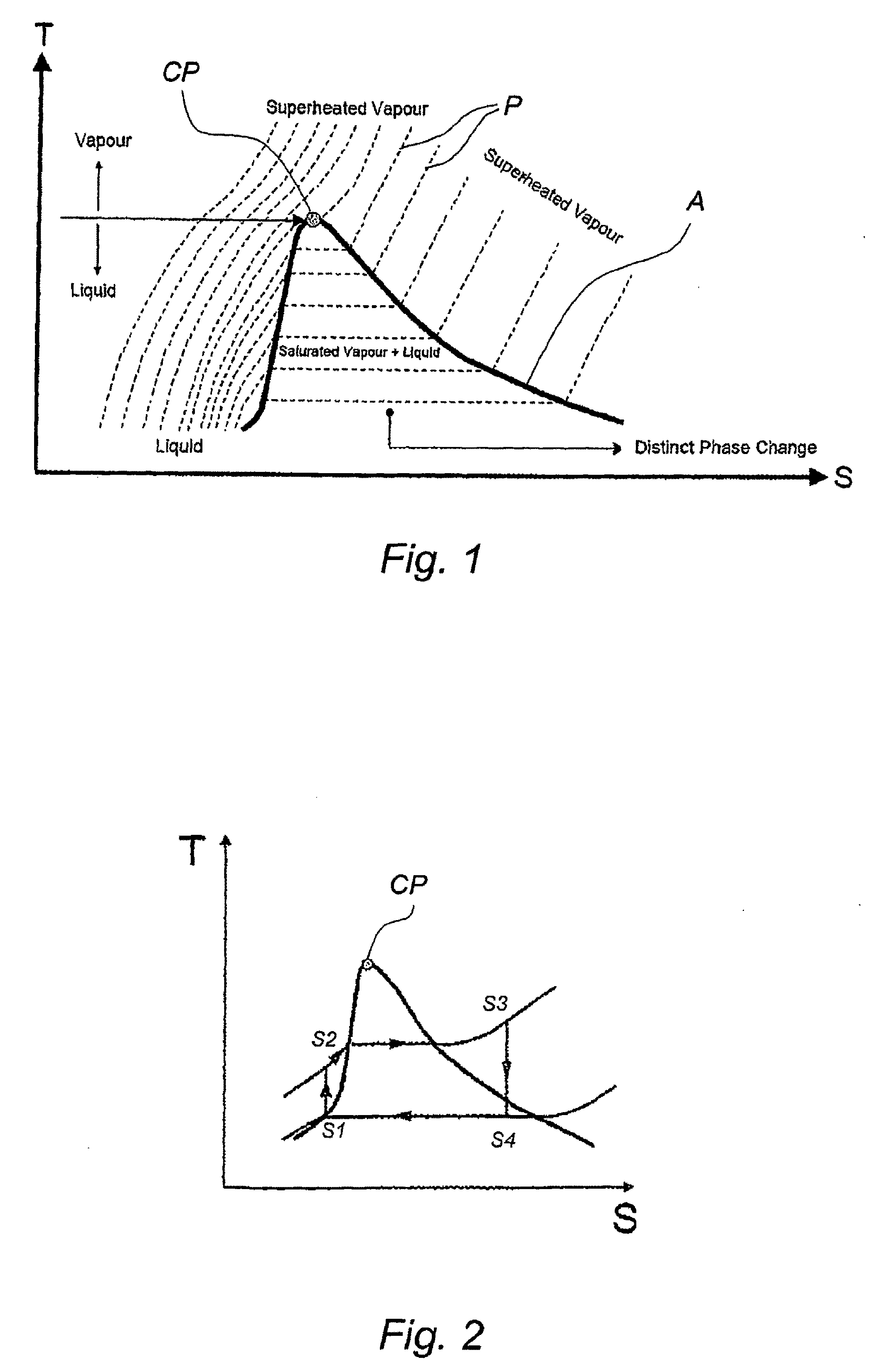
[0048]FIG. 1 is a phase diagram of a pure working fluid in the temperature (T)-entropy (S) domain. In the diagram, dotted lines P are isobars representing constant pressure. The saturation dome A defines the boundary at which the working fluid is in a saturated state. Most conventional power cycles, such as the Rankine cycle shown in FIG. 2, operate in or around the saturation phase of the working fluid as defined by the saturation dome A so that any phase change associated with the cycle takes place under constant pressure and temperature. This means that energy from the heat source is lost during phase changes of the working fluid within the saturation dome A. By contrast, the embodiments of the invention avoid these heat losses by operating above the saturation dome A.

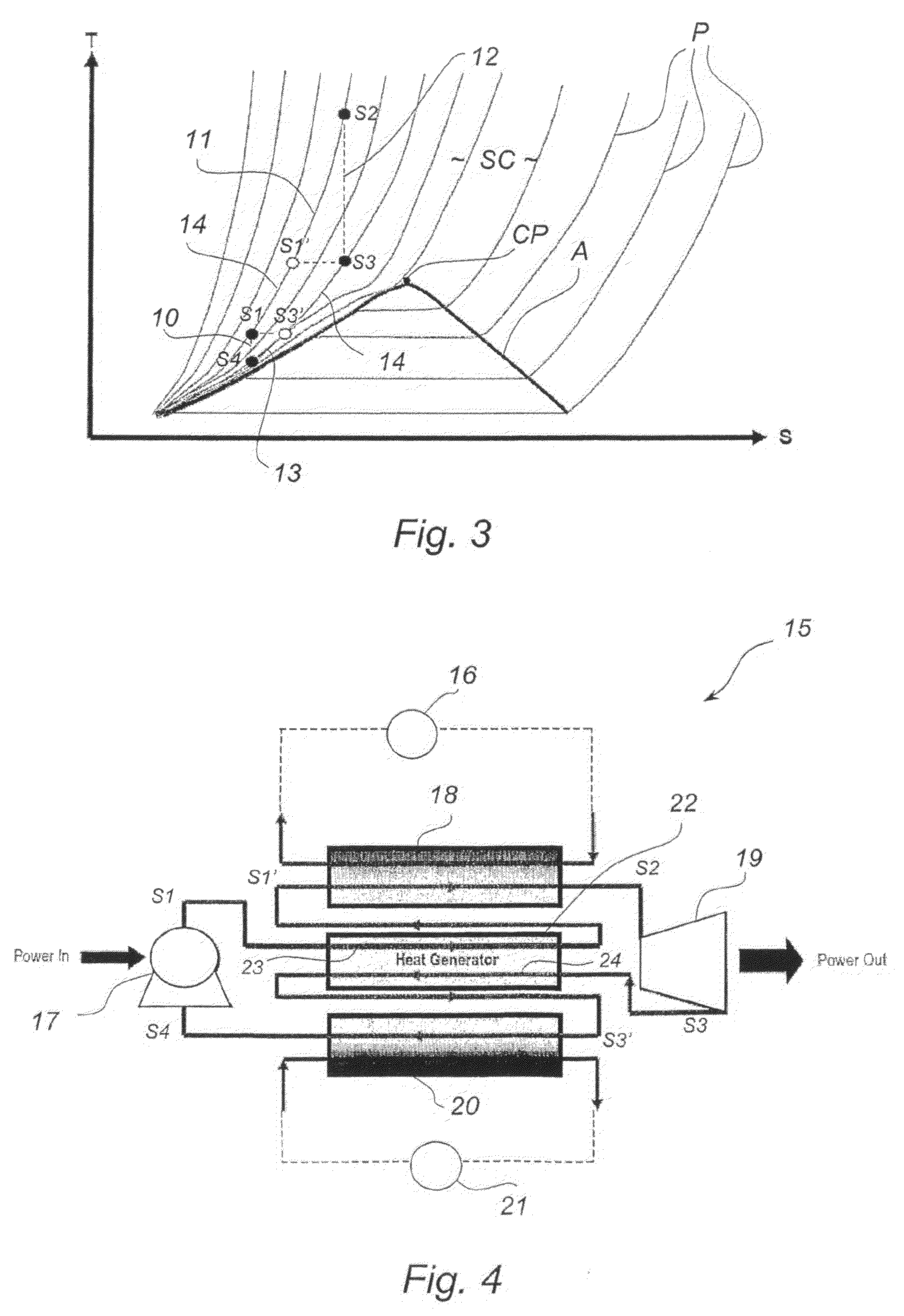
[0049]Referring to FIGS. 3 and 4, one embodiment of the invention is illustrated. As best shown in FIG. 3, the method of generating power from a heat source includes the step 10 of compressing a working fluid to inc...


PUM


Abstract

A method of generating power from a heat source, said method including: compressing (10) a working fluid to increase its temperature; exchanging (11) heat between said working fluid and said heat source to superheat said working fluid; expanding (12) said superheated working fluid to drive a turbine, thereby reducing its temperature; condensing (13) said working fluid to further reduce its temperature: and returning said working fluid to said compressing step (10), the method further including the step (14) of regenerating the heat of said working fluid wherein working fluid passing between said compressing step (10) and said heat exchanging step (11) exchanges heat with working fluid passing between said expanding step (12) and said condensing step (13); wherein said steps are performed in a thermodynamic cycle (S1-S1′-S2-S3-S3′-S4) within a supercritical region (SC) above the saturation dome (A) of said working fluid, and wherein said heat regenerating step (14) is performed under isenthalpic conditions to induce continuous heat exchange. A system for generating power from a heat source is also provided.

Description

FIELD OF THE INVENTION[0001]The present invention relates to a method and system for generating power from a heat source, and in particular to a method and system for generating power from a geothermal heat source.[0002]The invention has been developed primarily for use in generating power from a geothermal heat source and will be described hereinafter with reference to this application. However, it will be appreciated that the invention is not limited to this particular field of use.BACKGROUND OF THE INVENTION[0003]Any discussion of the prior art throughout the specification should in no way be considered as an admission that such prior art is widely known or forms part of common general knowledge in the field.[0004]Increased concern regarding the consumption of fossil fuels and reduction of greenhouse gases has led to research and development focusing on maximising the efficiency in power generation and on renewable energy resources. One renewable energy resource is geothermal ene...

Claims


Application Information

Patent Timeline
Patent Type & Authority Patents(United States)
IPC IPC(8): F01K25/08
CPCF01K25/08F01K25/10F01K3/06F02C1/10F02C1/06F28F27/02F28D17/00F03G7/04
Inventor MOGHTADERI, BEHDADDOROODCHI, ELHAM
Owner GRANITE POWER LTD
Why Eureka
Try Eureka