

Methods for reducing UV and dielectric diffusion barrier interaction
- Summary
- Abstract
- Description
- Claims
- Application Information
AI Technical Summary
Benefits of technology
Problems solved by technology
Method used
Image

Examples
Embodiment Construction
Introduction and Overview
[0020]In the following description, numerous specific details are set forth in order to provide a thorough understanding of the present invention. The present invention may be practiced without some or all of these specific details. In other instances, well known process operations have not been described in detail to not unnecessarily obscure the present invention. While the invention will be described in conjunction with the specific embodiments, it will be understood that it is not intended to limit the invention to the embodiments.
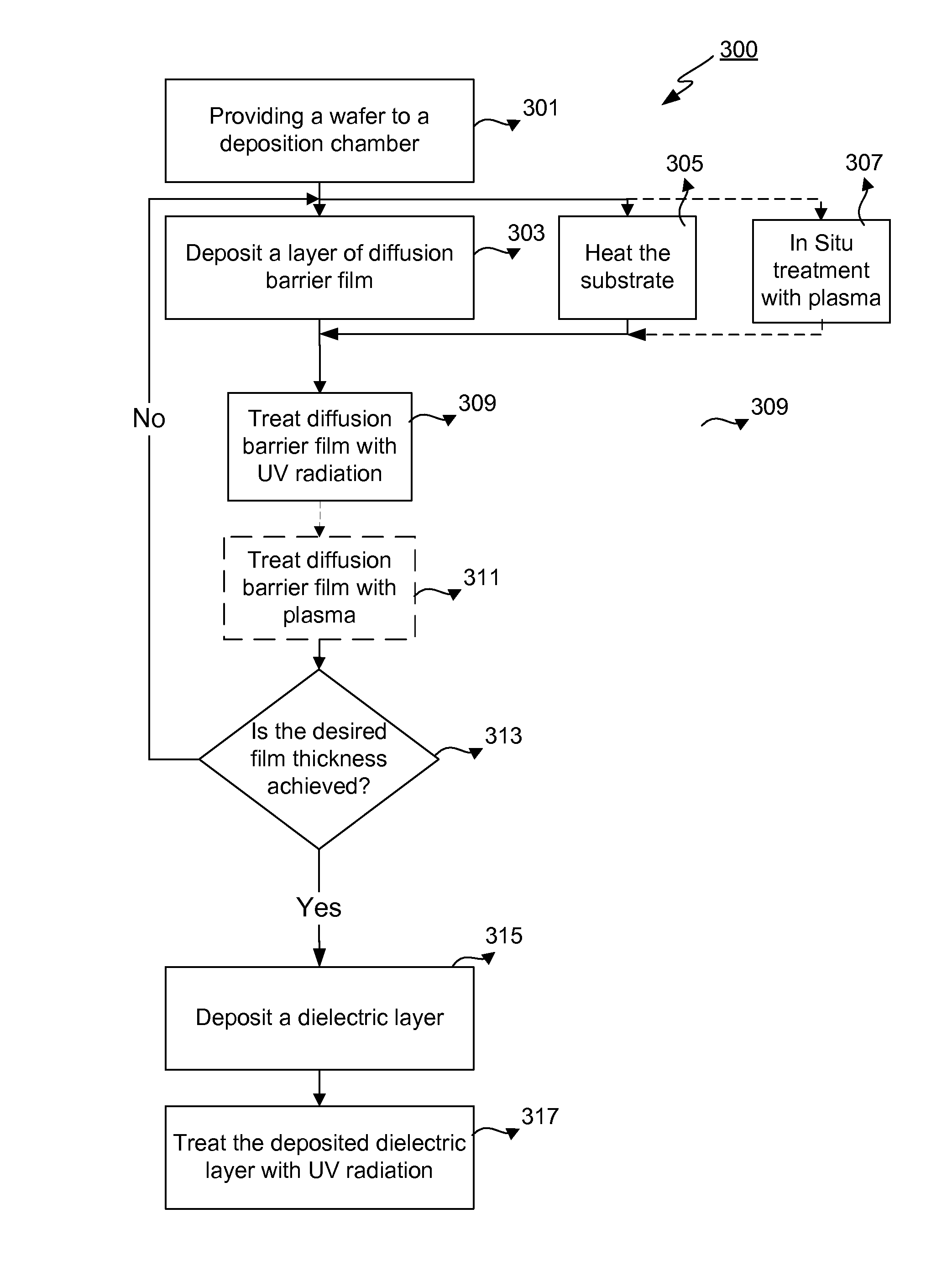
[0021]Stability of an underlying dielectric diffusion barrier during deposition and ultraviolet (UV) processing of an overlying dielectric layer is critical for successful integration. UV-resistant diffusion barrier layers are formed by depositing the layer in a hydrogen-starved environment. Diffusion barrier layers can be made more resistant to UV radiation by thermal, plasma, or UV treatment during or after deposition. Loweri...
PUM
 Abstract
Description
Claims
Application Information