Method for sensing a threat

a threat and detection method technology, applied in the field of threat detection, can solve the problems of not being able to draw a reliable conclusion about the existence of a threat, or even its signal failure, and achieve the effects of simple omnidirectional characteristic, increased validity of threat analysis, and extremely cost-effective operation

Active Publication Date: 2012-05-15
DIEHL STIFTUNG
View PDF10 Cites 6 Cited by
  • Summary
  • Abstract
  • Description
  • Claims
  • Application Information

AI Technical Summary

Benefits of technology

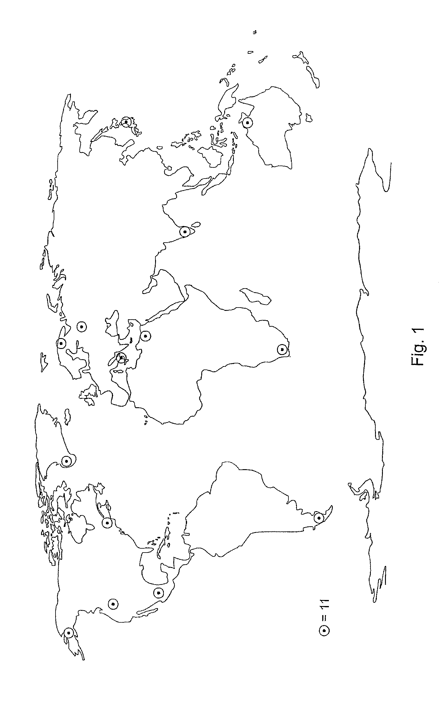
[0011]This is because a decision such as this can be made on a more justified basis the more accurately an image of the potential threat can be obtained from the various current irregularities which are recorded at widely different locations at the same time but virtually are uncorrelated with one another.
[0012]For evaluation purposes, it is particularly useful to compare the irregularities which occur with radiation aligned at a shallow angle synchronously in time with the irregularities from a steep incidence angle. The GALILEO transmitter group, which is currently being formed, is expediently used for the latter in the northern hemisphere because the major aspect of its satellite system is to cover the gap which is left by the GPS satellite system, which operates closer to the equator. The inclusion of the GPS satellite system in the evaluation is, on the other hand, particularly advantageous because this covers large areas, for example in the northern hemisphere, with a shallow incidence angle. In addition, it is possible to make use of the transmitters which are still available from the GLONASS satellite system, whose further upgrade has been announced.
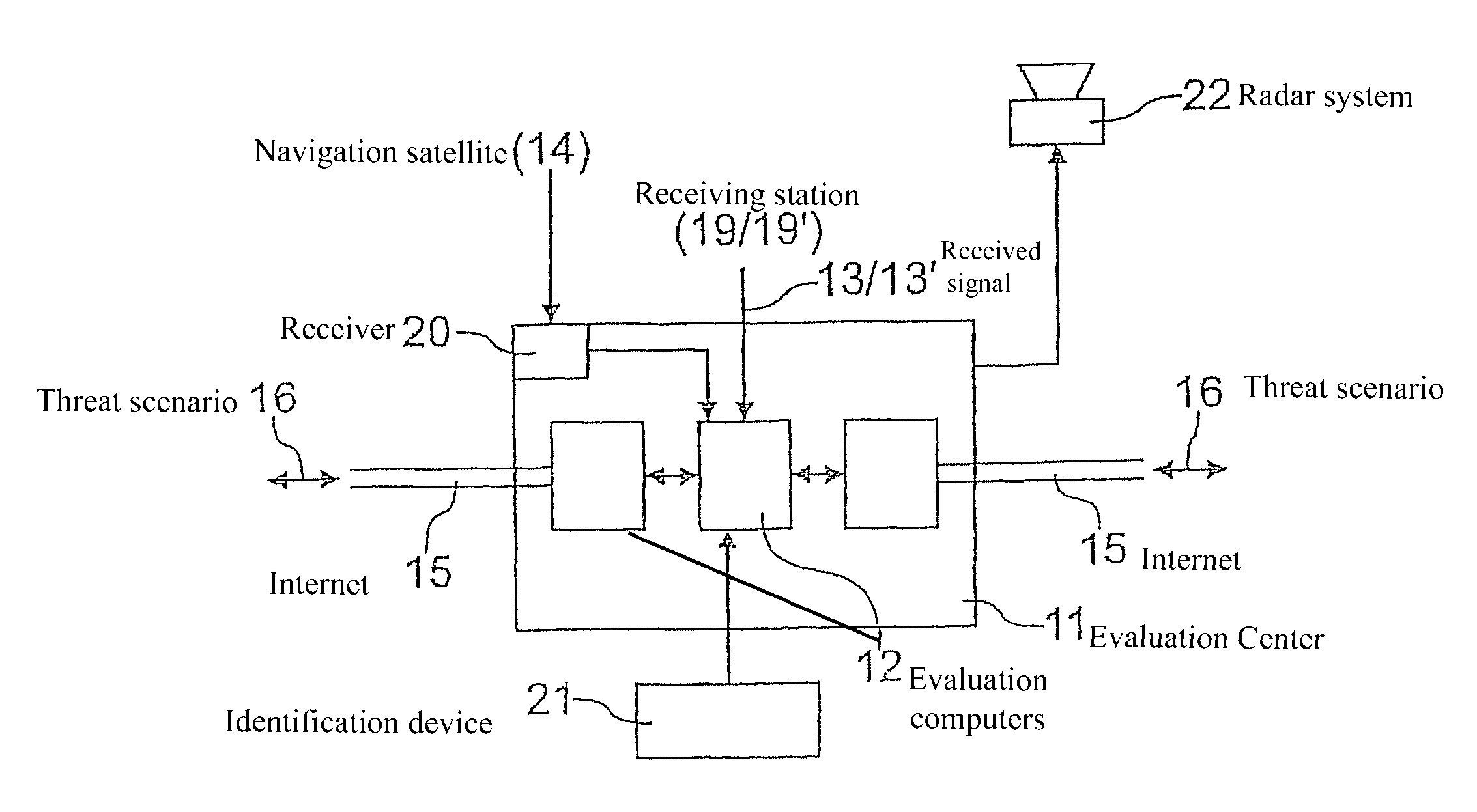
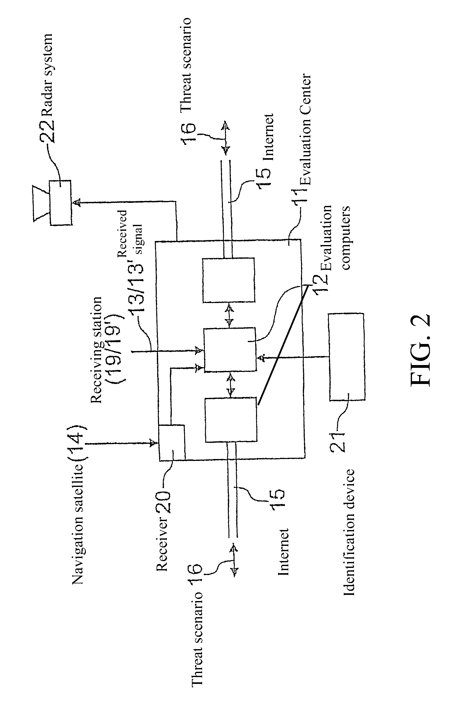
[0014]Because this spherical location distribution then also allows the position of the entity that is currently of interest to be found more accurately, receiving stations with better antenna equipment than a commercially available satellite navigation receiving device, in particular devices with very narrow beam directional antennas, can be aligned precisely with the spatial co-ordinates or at least the spatial sector of the entity which is of interest since it may represent a threat. At least one such device should be designed to obtain further information about the structure and the kinematics of the critical entity, for example of a projectile which is approaching the threatened object, with the capability to be operated at least temporarily as an active radar. This radar station should be located well away from the position of the potentially threatened object and the area relatively close to it, so that the temporary radar operation, that is to say the proof against self-betrayal which then no longer exists, does not result in any hazard at all to the object which may possibly be threatened at that time.
[0016]If at least a number of the receiving stations operate with antenna structures which differ from one another, non-matching irregularities can also be obtained for signature assessment purposes in all cases from approximately the same situation. This makes it possible to further increase the validity of the threat analysis since the recorded individual influences can then be provided with different weightings depending on the reception characteristics of the hardware.
[0018]This very large-area monitoring of the airspace necessarily also covers those influences which are exerted, for example, by airline traffic on the reception of satellite signals, that is to say from entities from which no threat exists. In order to identify false alarms resulting from them, and to suppress them as far as possible, it is expedient to observe and evaluate the airspace in the relatively near surrounding area, for example covering several hundred miles, around a potentially threatened object, with regard to the tracks of entities operating therein in the form of commercial aircraft. Because appropriate radar systems are generally not available to the objects, what is referred to as a virtual radar image is expediently created for this purpose, such as that already known from the tracking of the movement of commercial aircraft by means of UHF reception and decoding of their transponder signals. As simple UHF receiver and appropriate software, which is likewise commercially available, makes it possible in this way to obtain information in particular about the identity, flight number, flight path, position, altitude and movement rates, therefore allowing individual azimuth and elevation displays. In addition, it is also possible to use the flight data, disseminated over the Internet, for civil air traffic for alignment with specific commercial aircraft, or for verification of specific commercial aircraft, which are not entities that endanger the object to be protected.

Problems solved by technology

Specifically if, for example in the case of a receiving station which is operated in a mobile or stationary manner, the expected received signal from a specific transmitter in a transmitter group, specifically a satellite system, is currently found to have failed, it is not yet necessarily feasible to draw a reliable conclusion about the existence of a threat, or even its type, just from the current irregularity.
However, if a signal, even if, perhaps, it is an irregular signal, can be received at the same time at a receiving station which is positioned well away from this particular transmitter, then the signal failure that has been mentioned is then very highly probably not due to absorption but due to total reflection on the path of the radio link from the transmitter to the receiving station.

Method used


Image

  • Method for sensing a threat
  • Method for sensing a threat
  • Method for sensing a threat

Examples


Embodiment Construction

[0024]A virtually worldwide network comprising a relatively small number of evaluation centres 11 has locations, for example as shown in FIG. 1, in Alaska, on the west and east coasts of North America, in Mexico, Tierra del Fuego, Greenland, northern Finland, Russia, southern Italy, Egypt, South Africa, India, Japan and northern Australia. The evaluation centres 11 shown in FIG. 2 are fitted with evaluation computers 12 for actual received signals 13 from a plurality of navigation satellites 14 (FIG. 3) which are received at the same time and whose emitted signals are known, which are available for comparison with the disturbed received signals 13. The evaluation centres 11 are networked with one another via the Internet 15, in order to interchange typical threat scenarios 16 with one another. These threat scenarios 16 result from disturbances which are contained in the received signals 13 and are caused by potentially threatening entities 17 which may, in particular, be missiles on...


PUM


Abstract

A method employed for threat analysis based on the passive-radar principle, using the transmitter in navigation satellites, a plurality of receiving stations, which are operated distributed over wide regions, and at least one evaluation center. The receiving stations act as wake-up sensors, transmit their received signals to at least one evaluation center for comparison with expected signals from each navigation satellite and sensing of a threat. Depending on the result, radar systems are operated on a stationary or mobile basis, can then be used with their higher-quality antenna systems on a three-dimensional basis to obtain more precise details relating to a conspicuous entity and the threat which may possibly originate from it in a possible target region or to a mobile or stationary threatened object, and then to make it possible to decide on any currently required protective or defensive measures.

Description

BACKGROUND OF THE INVENTION[0001]1. Field of the Invention[0002]The invention relates to a method for sensing a potential threat to an object from an entity which passes radio links from navigation satellite transmitters to receiving stations.[0003]That method is distinguished in that, without requiring any three-dimensional alignment, it can quickly monitor the entry of an entity, from which a threat could originate, from a potentially threatened, also mobile object, from the hemispherical airspace. This is achieved on the basis of the passive-radar principle using the coherent signal structures which are emitted from the available navigation satellite transmitters, are highly constant over time and are known in the same way as the orbit data for non-geostationary satellites. Their current received signals are evaluated for irregularities in particular such as secondary signals that are dependent on back scatter in comparison to the received signals to be expected, with secondary s...

Claims


Application Information

Patent Timeline
Patent Type & Authority Patents(United States)
IPC IPC(8): G01S19/03G01S19/17G01S19/10G01S19/21G01S19/46
CPCG01S7/003G01S19/18G01S13/003G01S13/00
Inventor WESTPHAL, ROBERT
Owner DIEHL STIFTUNG
Why Eureka
Try Eureka