Electromagnetic interference filter and method for attaching a lead and/or a ferrule to capacitor electrodes

a technology of electromagnetic interference filter and capacitor electrode, which is applied in the direction of feeding through capacitors, fixed capacitor details, therapy, etc., can solve the problems of time-consuming and costly process of prior art metallization (also known as termination) on the outside diameter of the capacitor and into all of the capacitor feedthrough holes, and serious disruption of the proper operation of the pacemaker

Active Publication Date: 2012-05-15
WILSON GREATBATCH LTD
View PDF12 Cites 69 Cited by
  • Summary
  • Abstract
  • Description
  • Claims
  • Application Information

AI Technical Summary

Problems solved by technology

However, the lead wires can also undesirably act as an antenna and thus tend to collect stray electromagnetic interference (EMI) signals for transmission into the interior of the medical device.
Studies conducted by the United States Food and Drug Administration (FDA), Mount Sinai Medical Center and other researchers have demonstrated that stray EMI, such as radio frequency (RF) signals produced by cellular telephones, can seriously disrupt the proper operation of the pacemaker.
All of these situations can be dangerous or even life threatening for a pacemaker-dependent patient.
Application of the prior art metallization (also known as termination) on the capacitor outside diameter and also into all of the capacitor feedthrough holes is a time consuming and costly process.
While these processes tend to be very reliable, they are very expensive and time consuming.
However, the process of injecting a material through repeated centrifuge steps and then repeated microblast cleaning steps is very time consuming, costly, and tends to result in low process yields.
However, for a capacitor with a flat surface with lead wires extending through its inside passageways or through-holes, it is problematic to make a reliable electrical connection.
During re-flow operations, at high temperature these materials tend to migrate into undesirable positions.

Method used


Image

  • Electromagnetic interference filter and method for attaching a lead and/or a ferrule to capacitor electrodes
  • Electromagnetic interference filter and method for attaching a lead and/or a ferrule to capacitor electrodes
  • Electromagnetic interference filter and method for attaching a lead and/or a ferrule to capacitor electrodes

Examples


Embodiment Construction

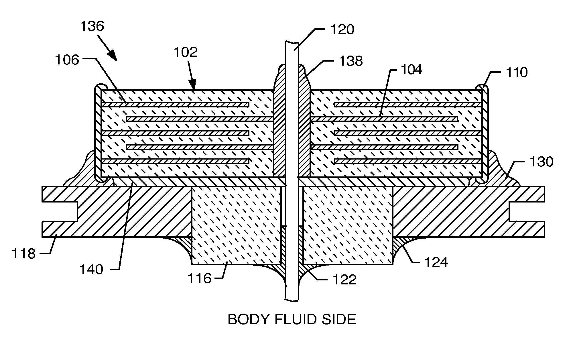
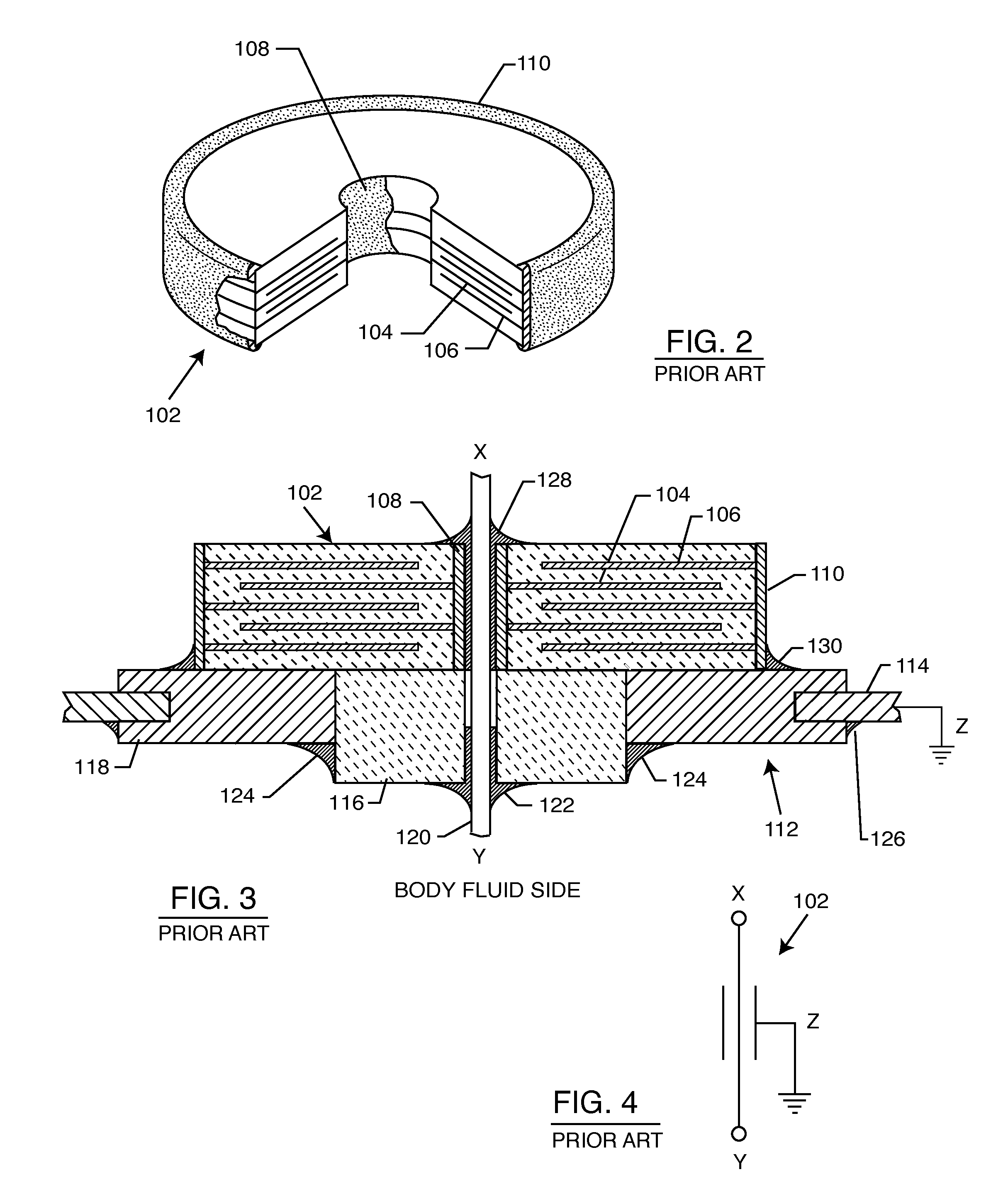
[0039]In the description that follows, functionally equivalent components generally have the same reference numbers throughout the drawings.

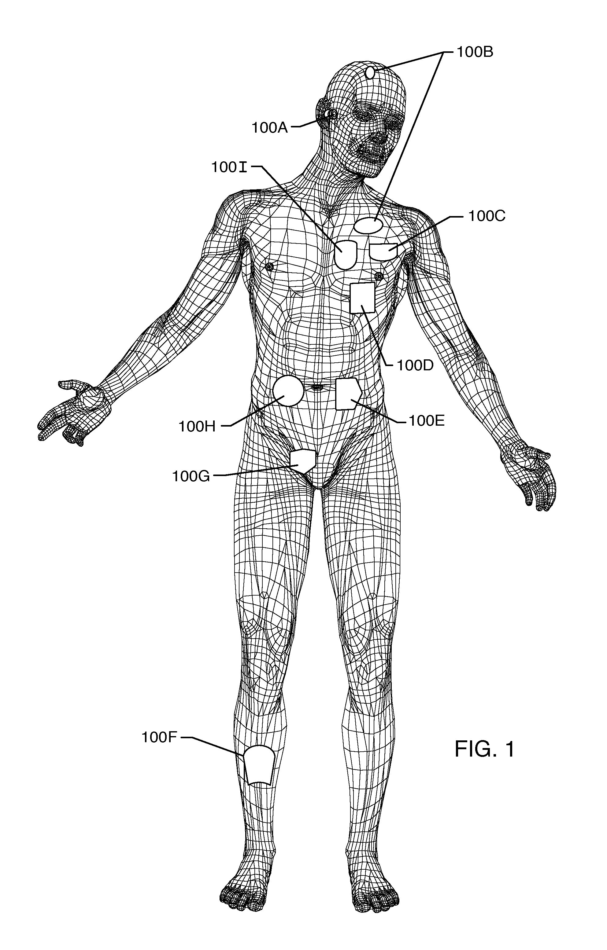
[0040]FIG. 1 is a wire formed diagram of a generic human body showing a number of implanted medical devices. 100A represents a family of hearing devices which can include the group of cochlear implants, piezoelectric sound bridge transducers and the like. 100B represent a variety of neurostimulators and brain stimulators. Neurostimulators are used to stimulate the Vagus nerve, for example, to treat epilepsy, obesity and depression. Brain stimulators are pacemaker-like devices and include electrodes implanted deep into the brain for sensing the onset of the seizure and also providing electrical stimulation to brain tissue to prevent the seizure from actually occurring. The lead wires associated with a deep brain stimulator are often placed using real time MRI imaging. Most commonly such lead wires are placed during real time MRI. 100C shows a car...


PUM

PropertyMeasurementUnit
conductiveaaaaaaaaaa
electrically conductiveaaaaaaaaaa
shrinkageaaaaaaaaaa

Abstract

A discoidal feedthrough capacitor has its active electrode plates disposed within a dielectric body so that an edge of the active electrode plates is exposed at a surface of a through-hole for a conductive lead. The conductive lead is conductively coupled to the exposed edge of the electrode plates without an intervening conductive termination surface. Similarly, a ground electrode plate set of the feedthrough capacitor may have an edge exposed at the outer periphery of the capacitor for conductively coupling the exposed edge of the ground electrode plate to a conductive ferrule without an intervening conductive termination surface.

Description

BACKGROUND OF THE INVENTION[0001]This invention relates generally to EMI filter terminal subassemblies and related methods of construction, particularly of the type used in active implantable medical devices (AIMDs) such as cardiac pacemakers, implantable defibrillators, cochlear implants, neurostimulators, active drug pumps and the like, which are designed to decouple and shield undesirable electromagnetic interference (EMI) signals from an associated device. More particularly, the present invention relates to an improved EMI filter terminal assembly and methods for directly attaching the electrode plates of a feedthrough capacitor to the associated lead wires and / or ferrule.[0002]Feedthrough terminal assemblies are generally well known for connecting electrical signals through the housing or case of an electronic instrument. For example, in implantable medical devices, the terminal pin assembly comprises one or more conductive terminal pins supported by an insulator structure for ...

Claims


Application Information

Patent Timeline
Patent Type & Authority Patents(United States)
IPC IPC(8): H01G4/35
CPCA61N1/3754H01G4/35H01G4/228A61N1/3718Y10T29/49204Y10T29/435
Inventor BRENDEL, RICHARD L.STEVENSON, ROBERT A.WOODS, JASON
Owner WILSON GREATBATCH LTD
Why Eureka
Try Eureka