
Clock and data recovery loop with ISI pattern-weighted early-late phase detection

a phase detection and pattern-weighted technology, applied in the field of signal phase detection and tracking, can solve the problems of phase detectors that adjust the phase in the wrong direction, the above-mentioned problems are compounded, and the performance of the detector is moderately affected, so as to reduce the probability, reduce the effect of isi, and mitigate the effects of inter-symbol interferen

Active Publication Date: 2012-05-15
MACOM CONNECTIVITY SOLUTIONS LLC
View PDF5 Cites 3 Cited by
  • Summary
  • Abstract
  • Description
  • Claims
  • Application Information

AI Technical Summary

Benefits of technology

[0015]Disclosed herein is a phase detector that weights data sequence patterns to mitigate against the effects of inter-symbol interference (ISI) in received data. Multiple data patterns or sequences are detected and assigned different ISI weights, which are used by the phase detector to adjust the recovered clock phase. ISI patterns that have a lower probability of being correct are assigned with less weight, and vice versa.

Problems solved by technology

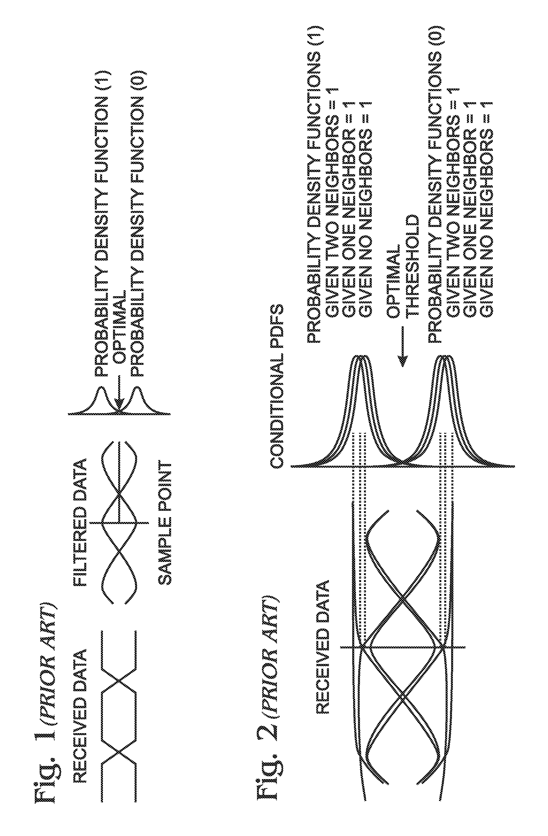
For small degrees of spreading these effects of this can be limited to the nearest neighbors with modest degradation in performance.
The above-mentioned problems are compounded if the receiver must recover the clock from the incoming data stream.
That is, ISI on the received data may cause the phase detector to adjust the phase in the wrong direction if all possible ISI patterns are treated equally.
Clock jitter results from the inability of a phase detector to properly lock or track phase, which becomes another source of increased bit error rate (BER).
However, it is not practical to perform an analog-to-digital (A / D) conversion at high serial stream data rates.
Further, there is a latency associated with processing of digital signals.
The inherent latency of conventional digital circuitry limits the use of purely digital oscillator circuitry to relatively low frequencies.

Method used


Image

  • Clock and data recovery loop with ISI pattern-weighted early-late phase detection
  • Clock and data recovery loop with ISI pattern-weighted early-late phase detection
  • Clock and data recovery loop with ISI pattern-weighted early-late phase detection

Examples


Embodiment Construction

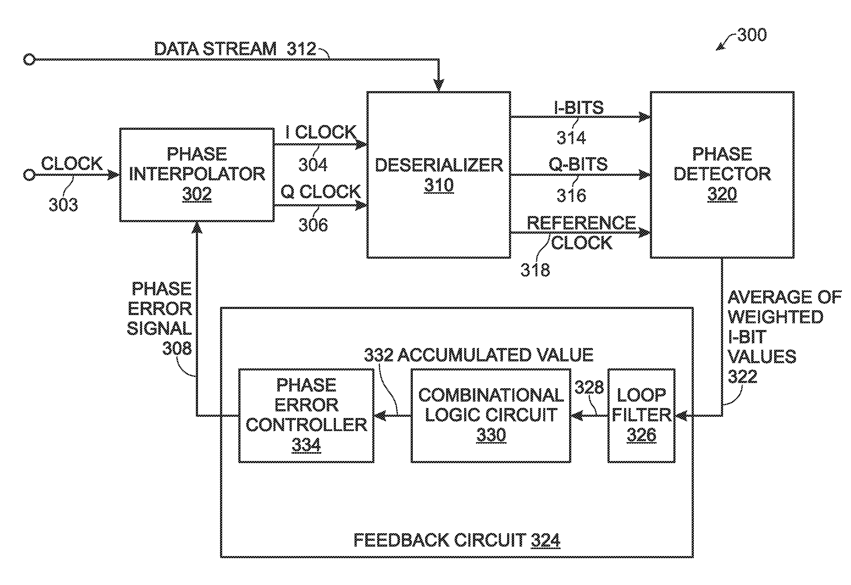
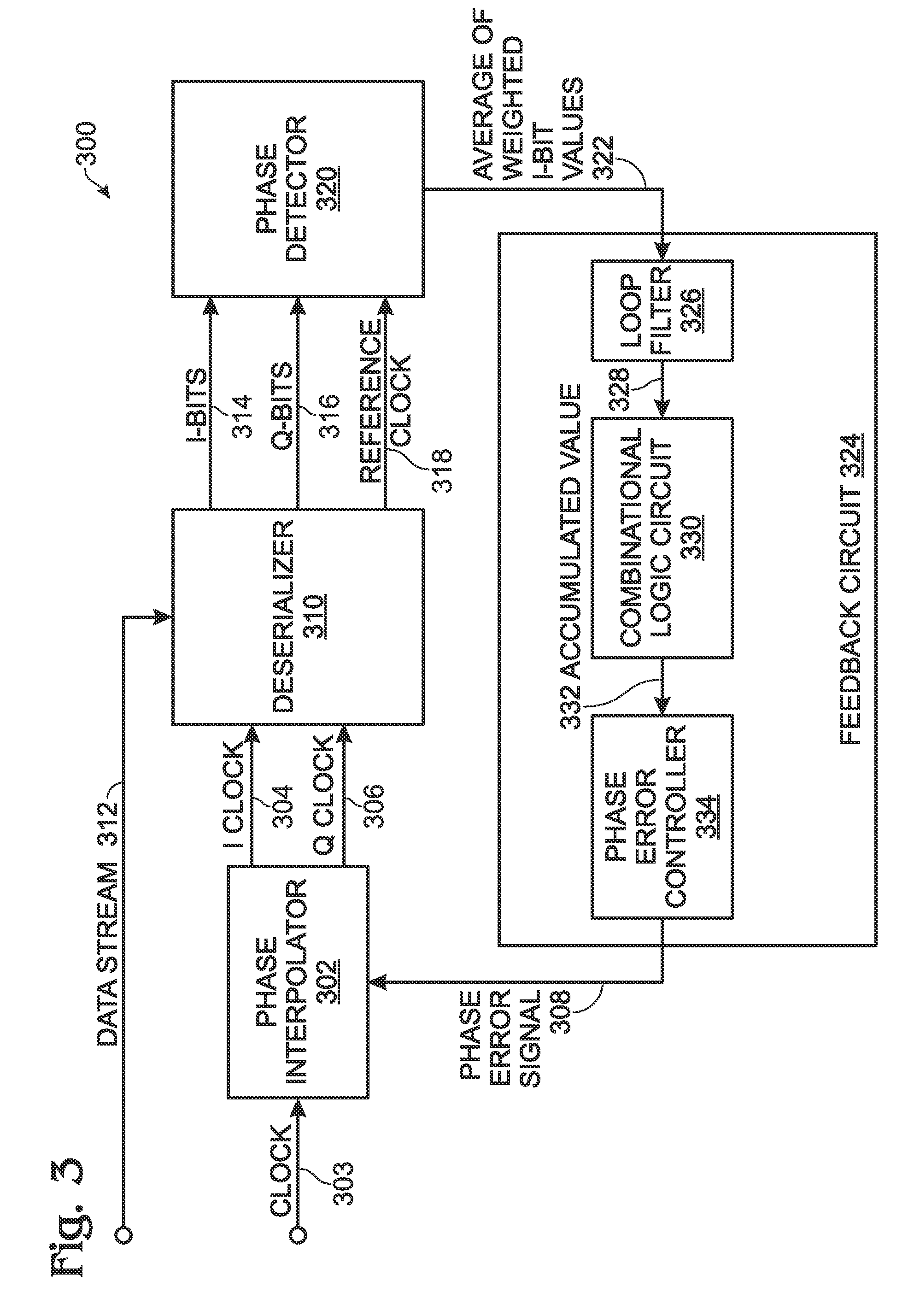
[0027]FIG. 3 is a schematic block diagram of a clock and data recovery (CDR) device with a system for the guaranteed acquisition and tracking of a clock signal using an inter-symbol interference (ISI) pattern-weighted early-late phase detector. The system 300 comprises a phase interpolator 302 having an input on line 303 to accept a fixed frequency clock, an output on line 304 to supply an I clock signal, an output on line 306 to supply a Q clock signal having a fixed delay with respect to the I clock signal, and an input an input on line 308 to accept a digital phase error signal. The I clock has the same frequency as the clock on line 303, but the frequency of the I (and Q) clock varies in response to the phase error signal. In one aspect, the phase interpolator 302 generates a Q clock signal that is delayed 90 degrees in phase from the I clock signal. However, the system is not necessarily limited to this value. Neither is the system limited to the Q clock having a fixed phase re...


PUM


Abstract

An inter-symbol interference (ISI) pattern-weighted early-late phase detector is provided. I and Q clocks are generated, where the Q clock has a fixed phase delay with respect to the I clock. The I clock frequency is divided by n, creating a reference clock. A serial data stream is sequentially sampled with the I and Q clocks, creating digital I-bit and Q-bit values, respectively. The I-bit values and Q-bit values are segmented into n-bit digital words. In response to analyzing the I-bit and Q-bit values, I clock phase corrections are identified. Also identified are bit sequence patterns associated with each I-bit value. Each I-bit value is weighted in response to the identified bit sequence pattern and the identified I clock phase correction. A phase error signal is generated by averaging the weighted I-bit values for each n-bit digital word, and I clock is modified in phase.

Description

RELATED APPLICATIONS[0001]This application is a continuation-in-part of a pending application entitled, SINGLE CLOCK CYCLE FIRST ORDER LIMITED ACCUMULATOR FOR SUPPLYING WEIGHTED CORRECTIONS, invented by Do et al., Ser. No. 12 / 399,861, filed Mar. 6, 2009;[0002]which is a continuation-in-part of a pending application entitled, FLEXIBLE ACCUMULATOR FOR RATIONAL DIVISION, invented by Do et al., Ser. No. 11 / 954,325, filed Dec. 12, 2007. These applications are incorporated herein by reference.BACKGROUND OF THE INVENTION[0003]1. Field of the Invention[0004]This invention generally relates to signal phase detection and tracking and, more particularly, to a system and method to optimize an early / late phase detector using pattern weighting.[0005]2. Description of the Related Art[0006]FIG. 1 is a diagram illustrating a signal recovered from a binary symmetric, non-dispersive channel in the presence of noise (prior art). Conventionally, the signal is filtered with a transfer function matched to...

Claims


Application Information

Patent Timeline
Patent Type & Authority Patents(United States)
IPC IPC(8): H04L7/00H04L25/00H04L25/40
CPCH04L7/033
Inventor DO, VIET LINHFU, WEI
Owner MACOM CONNECTIVITY SOLUTIONS LLC
Learn More