Spin transfer torque triad for non-volatile logic gates

a non-volatile, logic gate technology, applied in pulse techniques, magnetic bodies, instruments, etc., can solve the problems that conventional magnetic memories or devices (e.g., mram) that are used to replace solid state memories such as dynamic random access memory (dram), static random access memory (sram), and flash memory, are not capable of executing logi

Inactive Publication Date: 2012-06-12
RGT UNIV OF CALIFORNIA
View PDF2 Cites 21 Cited by
  • Summary
  • Abstract
  • Description
  • Claims
  • Application Information

AI Technical Summary

Benefits of technology

[0012]One or more embodiments of the present invention comprise connecting STT-MRAM to a single domain nanoscale magnet in order to execute a logic function, and using the STT-MRAM to both read from and write to the single domain nanoscale magnet.

Problems solved by technology

However, conventional magnetic memories or devices (e.g., MRAM) that are used to replace solid state memories such as Dynamic Random Access Memory (DRAM), Static Random Access Memory (SRAM), and flash memory, are not capable of executing logic.

Method used


Image

  • Spin transfer torque triad for non-volatile logic gates
  • Spin transfer torque triad for non-volatile logic gates
  • Spin transfer torque triad for non-volatile logic gates

Examples


Embodiment Construction

[0040]In the following description of the preferred embodiment, reference is made to the accompanying drawings which form a part hereof, and in which is shown by way of illustration a specific embodiment in which the invention may be practiced. It is to be understood that other embodiments may be utilized and structural changes may be made without departing from the scope of the present invention.

[0041]Overview

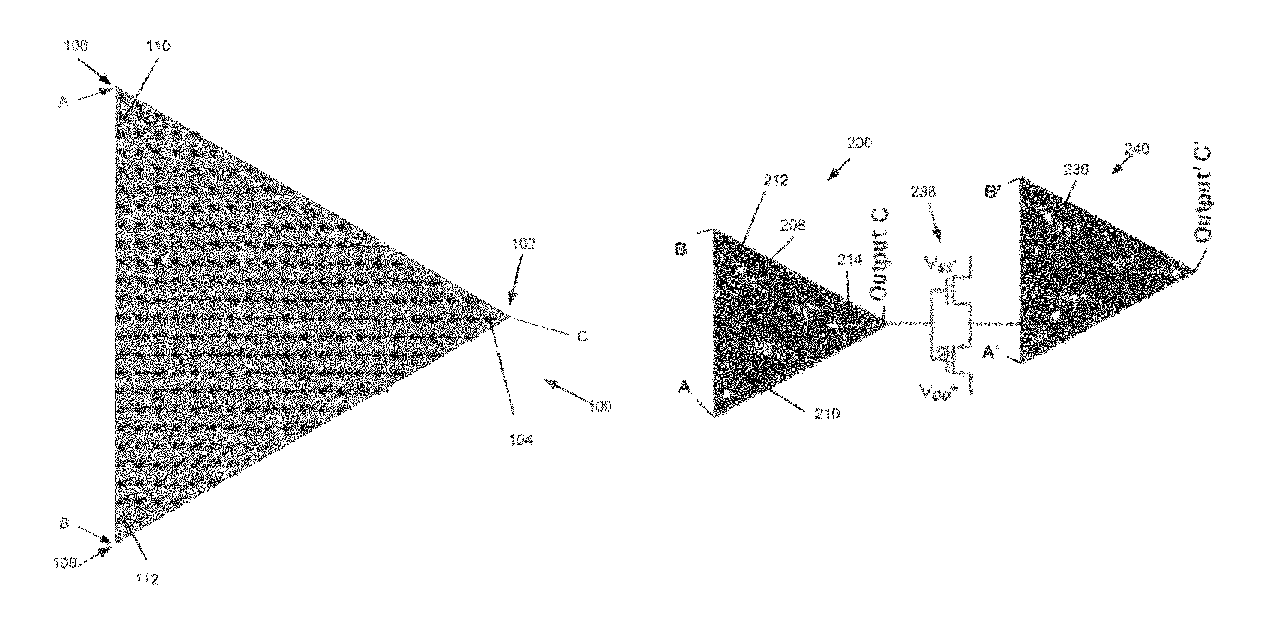
[0042]One concept of the present invention is the separation of the read and write functions of the STT-MRAM, and connection of STT-MRAMs by a shared single domain magnet, thereby achieving non-volatile logic.

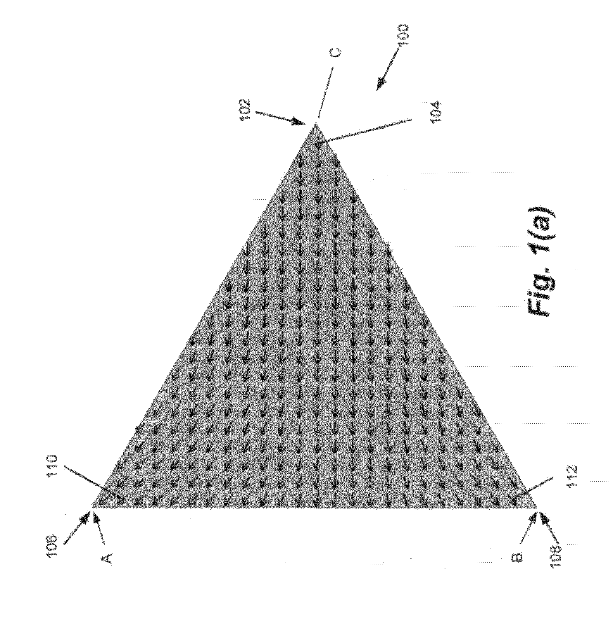
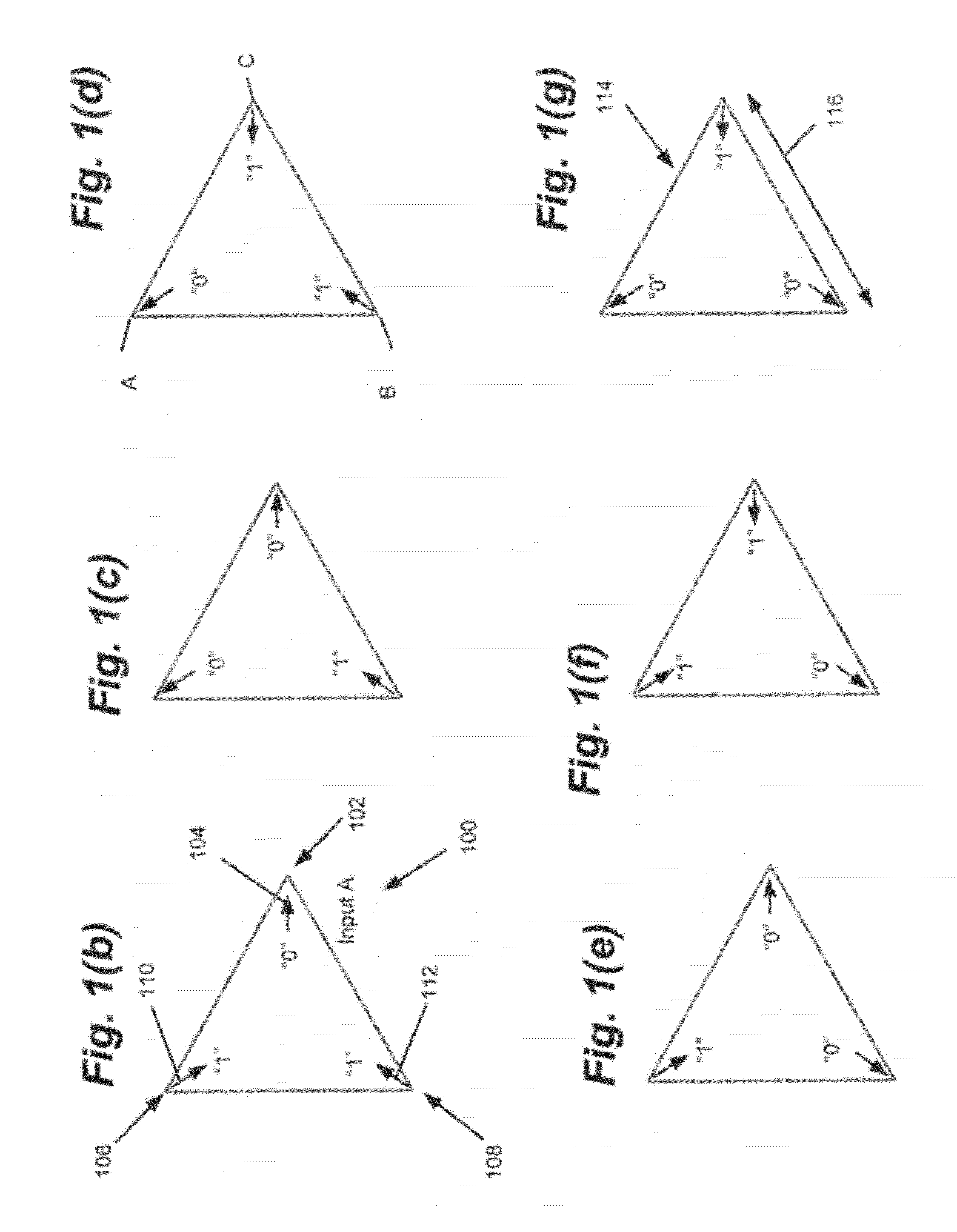
[0043]Strong shape induced magnetic anisotropy defines six different magnetization alignment ground states of a single domain ferromagnetic triangle. Local magnetization direction at the triangle vertices defines logical “0”, pointing inwards, and logical “1” pointing outwards, from the vertices of the triangle. The present invention defines one vertex as the output and t...


PUM


Abstract

A non-volatile logic gate, including a magnetic material having a shape induced magnetic anisotropy, wherein a shape of the magnetic material has a first vertex, a second vertex, and a third vertex and supports a single magnetic domain; regions of the magnetic material including a first input region adjacent the first vertex, a second input region adjacent the second vertex, and an output region adjacent a third vertex; the first input region for receiving a first logic input to the logic gate, the second input region for receiving a second logic input to the logic gate, and the output region for outputting at least one logic output of the logic gate; and the shape induced magnetic anisotropy determining at least part of a truth table for the logic gate, so that the logic gate produces the at least one logic output from the logic inputs using the shape.

Description

BACKGROUND OF THE INVENTION[0001]1. Field of the Invention[0002]This invention relates to logic gates, digital electronics for signal processing, storage and computation, and methods of fabricating the same.[0003]2. Description of the Related Art[0004](Note: This application references a number of different publications as indicated throughout the specification by one or more reference numbers within brackets, e.g., [x]. A list of these different publications ordered according to these reference numbers can be found below in the section entitled “References.” Each of these publications is incorporated by reference herein.)[0005]Spin Transfer Torque (STT) devices and spin valves are well documented in the literature. A spin valve device comprises a first conductive magnetic layer (fixed layer) and a second conductive magnetic layer (free layer), separated by a spacer layer, wherein the fixed layer, free layer, and spacer layers produce a device that exhibits Giant Magneto Resistance ...

Claims


Application Information

Patent Timeline
Patent Type & Authority Patents(United States)
IPC IPC(8): H03K19/20
CPCH01F10/3254H01F41/308B82Y40/00H01L43/08H01L43/12H03K19/16H03K19/20H01F10/3272H01F10/329H01L27/228H01L29/82H01L29/0665H10B61/22H10N50/10
Inventor KOZHANOV, ALEXANDERALLEN, S. JAMESPALMSTROM, CHRISTOPHER
Owner RGT UNIV OF CALIFORNIA
Why Eureka
Try Eureka