Implantable ocular microapparatus to ameliorate glaucoma or an ocular overpressure causing disease

a technology of ocular microapparatus and ocular overpressure, which is applied in the field of opthalmologic surgery, can solve the problems of high resistance, inadequate material, and insufficient size of the implant, and achieve the effect of avoiding hypotony and increasing resistance, and high resistan

Active Publication Date: 2012-06-26
CONSEJO NAT DE INVESTIGACIONES CIENTIFICAS Y TECH +1
View PDF13 Cites 25 Cited by
  • Summary
  • Abstract
  • Description
  • Claims
  • Application Information

AI Technical Summary

Benefits of technology

[0013]miniaturization of the implant using MEMS technology to make the size of the implant small enough, to avoid that micro movements cause reactions of the surrounding tissue (fibrosis) obstructing drainage and to allow adding other functionalities such as actuator / sensor.
[0016]To avoid hypotony and increase of resistance by fibrosis and particle obstruction by an actuator / sensor system with large displacements of the actuator / valve by using low rigidity polymeric materials in order to attain an opening that allows passing proteins and cells, together with the chance of a pumping mode in case of high resistance to flow as in case of advanced glaucoma or obstruction.
[0018]Reliable design that allows a long lifetime of the implant;
[0028]This material allows an opening of the microvalve big enough to drain particles that may obstruct the device. The power consumption is minimized as it is a cuasi-stable mechanism, a feature shown by this material and not by those disclosed in other patents (the term ‘cuasi-stable’ as used herein means that practically current is only consumed when switching between its two states as in one state—closed—there is no voltage and no consumption and in the other—open—a constant potential is kept and there could be little consumption of current by losses).
[0030]The use of the microcontroller allows incorporating additional features, such as adjusting externally the overpressure threshold by a telemetric link through which, also, electrical energy is transferred to a power supply that powers the implant. The power supply may be passive, i.e. it is transferred telemetrically to the implant components without own storage, or preferably active, having a cell within the implant telemetrically rechargeable, conveniently by an inductive coupling.

Problems solved by technology

However, said implants have shown so far some drawbacks, such as:the implant size is not small enough (lower than 1 cm) nor material are adequate to avoid fibrosis (see, Lim et al, Glaucoma drainage devices; past, present and future), Br J Ophthalmol 1998; 82:1083-1089)Surgery is not able to optimize or turn intraocular pressure predictable, resulting in hypotony or high resistance to flow (see, Q H. Nguyen, ‘Avoiding and managing complications of glaucoma drainage implants’, Curr Opin Ophthalmol 15:147-150, 2004)Intraocular pressure varies during the day, a variation that can not be compensated by passive valves (see, Kitazawa Y, Horie T.
Unfortunately, the abovementioned implants have biocompatibility and size problems as the previous ones that do not allow meeting design requirements.
Problems such as malfunctioning and obstruction have not been addressed by said patents.

Method used


Image

  • Implantable ocular microapparatus to ameliorate glaucoma or an ocular overpressure causing disease
  • Implantable ocular microapparatus to ameliorate glaucoma or an ocular overpressure causing disease
  • Implantable ocular microapparatus to ameliorate glaucoma or an ocular overpressure causing disease

Examples


Embodiment Construction

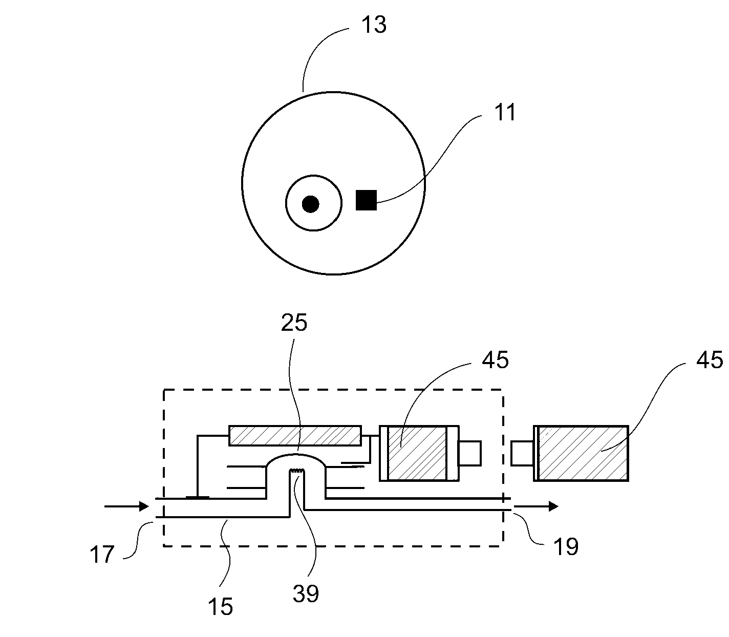
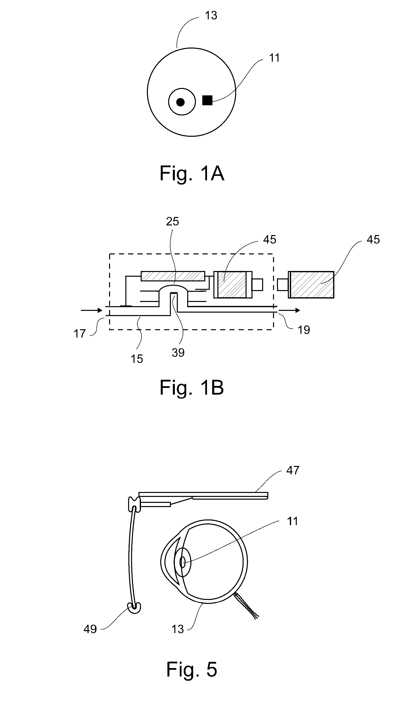
[0040]FIG. 1A shows schematically the different blocks comprising the microapparatus 11 of the present invention, which is surgically implanted to detect and correct glaucoma in an eye and in FIG. 1B the different blocks that conform the microapparatus 11. The microapparatus 11 uses a silicon rubber tube 15 having an inlet end 17 which is implanted in fluid communication with the aqueous humor in the ocular globe 13, more specifically in the sclera, a few millimeters from the corneal limb. The discharge end 19 may be free so that the drained fluid is absorbed by surrounding tissue.

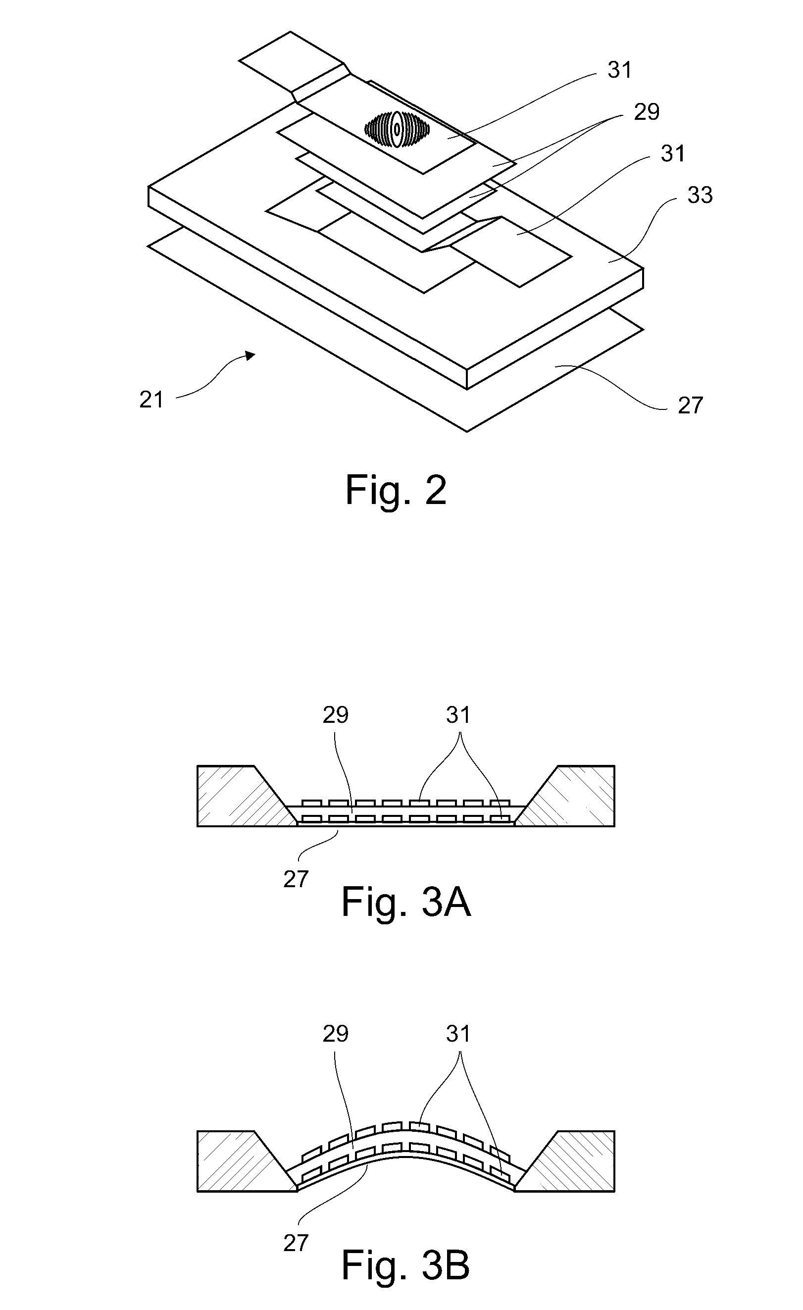
[0041]Around the drainage end 19 of conduit 15 there is a valve comprised by a membrane made of dielectric material disposed as a diaphragm 21 that normally (i.e. under normal pressure in the eye 13) closes tube 15. At a middle portion of the drainage tube 15 there is a sensor membrane 23 made of electro conductor material the ohmic resistance of which varies with the deformation the membrane 23 is subject...


PUM


Abstract

A microapparatus (11) implantable in the eye (13) includes a cuasi-bistable microvalve (21) commanded by an intraocular pressure sensor (23) in situ. The microvalve mechanism includes a diaphragm (27) made of a conjugated polymer (29) that shows high deformation and biocompatibility capabilities and which volume depends from the electric potential applied by its pair of electrodes (31). The sensor and actuator-valve are coupled to a drainage conduit (15), the first to deform by the pressure in the ocular globe and the second in a position of buckling to normally close the drainage conduit. The sensor has a membrane of conductive polymeric material with these same properties and whose ohmic resistance varies with the mechanical deformation produced by the ocular pressure.

Description

TECHNICAL FIELD[0001]This invention is applicable to opthalmologic surgery and refers to amelioration or eventual cure of high intraocular pressure related to glaucoma.[0002]Glaucoma is a general term for a progressive disease that leads to blindness caused by a gradual, sometimes rapid, increase of the intraocular pressure. This pressure increase is considered a very important risk factor. It is estimated that about 67 million people suffers from this disease in the world.BACKGROUND ART[0003]There are drug and surgical treatments to decrease intraocular pressure. When therapy and surgery do not work, implants are used (in the form of bypasses known in the field as ‘shunts’) with passive valves that drain the intraocular liquid (aqueous humor) to the outside through tubes and plates. See, for example, Lim, K. S., ‘Glaucoma drainage devices, past, present and future’, Br. J. Ophtalmol (1968), 82:1083-1089 or the international patent (PCT) WO99 / 66871, which describes a device—of about...

Claims


Application Information

Patent Timeline
Patent Type & Authority Patents(United States)
IPC IPC(8): A61F2/14A61M5/00
CPCA61F9/00781
Inventor GUARNIERI, FABIO ARIEL
Owner CONSEJO NAT DE INVESTIGACIONES CIENTIFICAS Y TECH
Why Eureka
Try Eureka