Mitigation of membrane degradation by multilayer electrode

a multi-layer electrode and membrane degradation technology, applied in cell components, electrochemical generators, transportation hydrogen technology, etc., can solve the problems of increasing reduce the hydrogen and/or oxygen partial pressure, reduce the fluoride release rate, and reduce the degradation of the membrane

Active Publication Date: 2012-06-26
GM GLOBAL TECH OPERATIONS LLC
View PDF12 Cites 3 Cited by
  • Summary
  • Abstract
  • Description
  • Claims
  • Application Information

AI Technical Summary

Benefits of technology

[0011]In accordance with the teachings of the present invention, an MEA for a fuel cell is disclosed that employs multiple catalyst layers to reduce the hydrogen and / or oxygen partial pressure at the membrane so as to reduce the fluoride release rate from the membrane and reduce membrane degradation. An anode side multi-layer catalyst configuration is provided at the anode side of the MEA. The anode side multi-layer configuration includes an anode side under layer positioned against the membrane and including a catalyst, an anode side middle layer positioned against the anode side under layer and not including a catalyst and an anode side catalyst layer positioned against the anode side middle layer and opposite to the anode side under layer and including a catalyst, where the amount of catalyst in the anode side catalyst layer is greater than the amount of catalyst in the anode side under layer.

Problems solved by technology

The hydrogen fluoride corrodes stainless steel bipolar plates, which generates more ferric and ferrous ions, increasing the production of the hydroxyl free radicals, and thus further increasing the degradation of the membrane.

Method used


Image

  • Mitigation of membrane degradation by multilayer electrode
  • Mitigation of membrane degradation by multilayer electrode
  • Mitigation of membrane degradation by multilayer electrode

Examples


Embodiment Construction

[0019]The following discussion of the embodiments of the invention directed to an MEA for a fuel cell that includes multiple catalyst layers at one or both of the anode side and the cathode side of the membrane to reduce hydrogen and / or oxygen partial pressure at the membrane is merely exemplary in nature, and is in no way intended to limit the invention or its applications or uses.

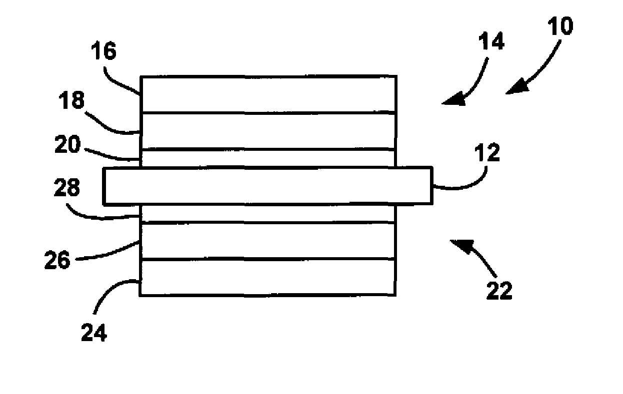
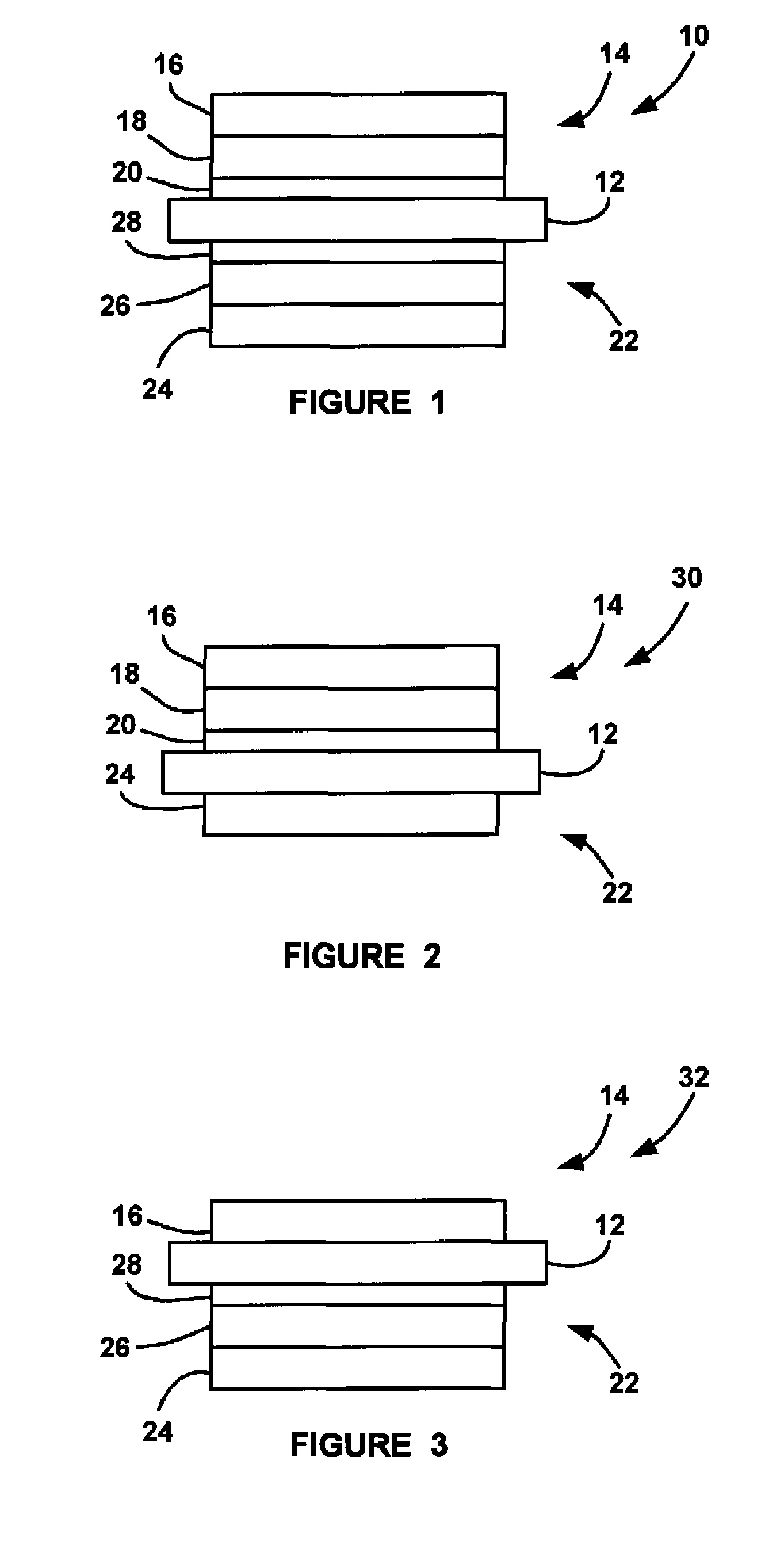
[0020]FIG. 1 is a plan view of an MEA 10 including a proton conducting membrane, such as perfluorosulfonic acid membrane 12, such as the commercially available Nafion® membrane. The MEA 10 would be part of a proton exchange membrane fuel cell of the type discussed above, and could be part of a fuel cell stack in a fuel cell system for a vehicle. According to the invention, the MEA 10 includes an anode side 14 having a catalyst layer 16, a middle layer 18 and an under layer 20. Likewise, a cathode side 22 of the MEA 10 includes a catalyst layer 24, a middle layer 26 and an under layer 28.

[0021]Conventional...


PUM

PropertyMeasurementUnit
thicknessaaaaaaaaaa
thickaaaaaaaaaa
thickaaaaaaaaaa

Abstract

An MEA for a fuel cell that employs multiple catalyst layers to reduce the hydrogen and / or oxygen partial pressure at the membrane so as to reduce the fluoride release rate from the membrane and reduce membrane degradation. An anode side multi-layer catalyst configuration is positioned at the anode side of the MEA membrane. The anode side multi-layer catalyst configuration includes an anode side under layer positioned against the membrane and including a catalyst, an anode side middle layer positioned against the anode side under layer and not including a catalyst and an anode side catalyst layer positioned against the anode side middle layer and opposite to the anode side under layer and including a catalyst, where the amount of catalyst in the anode side catalyst layer is greater than the amount of catalyst in the anode side under layer.

Description

BACKGROUND OF THE INVENTION[0001]1. Field of the Invention[0002]This invention relates generally to an MEA for a fuel cell that includes a multi-layer catalyst configuration for decreasing the hydrogen and / or oxygen partial pressure at the cell membrane and, more particularly, to an MEA for a fuel cell that includes multiple catalyst layers on the anode side and / or cathode side of the cell membrane that reduces the hydrogen and oxygen partial pressure at the membrane so as to decrease membrane degradation.[0003]2. Discussion of the Related Art[0004]Hydrogen is a very attractive fuel because it is clean and can be used to efficiently produce electricity in a fuel cell. A hydrogen fuel cell is an electro-chemical device that includes an anode and a cathode with an electrolyte therebetween. The anode receives hydrogen gas and the cathode receives oxygen or air. The hydrogen gas is dissociated in the anode to generate free protons and electrons. The protons pass through the electrolyte ...

Claims


Application Information

Patent Timeline
Patent Type & Authority Patents(United States)
IPC IPC(8): H01M8/10
CPCH01M4/8605H01M4/8642H01M4/8657H01M8/04261H01M8/1004Y02T90/32H01M2250/20H01M2300/0082Y02E60/521H01M8/04197Y02E60/50Y02T90/40
Inventor BRENNER, ANNETTE M.GASTEIGER, HUBERT A.GU, WENBINLEISTRA, JAMESLITTEER, BRIAN A.LIU, HANYAN, SUSAN G.ZHANG, JINGXIN
Owner GM GLOBAL TECH OPERATIONS LLC
Why Eureka
Try Eureka