
Use of acoustic signals for measuring membrane fouling in spiral wound modules

a technology of spiral wound module and acoustic signal, which is applied in the direction of vibration measurement in solids, water/sewage treatment, osmosis/dialysis, etc., can solve the problems of reduced membrane flux and selectivity, high cleaning cost, and common problem of membrane fouling, so as to optimize module performance, maintenance, replacement, and/or cleaning

Active Publication Date: 2012-07-03
DOW GLOBAL TECH LLC
View PDF9 Cites 35 Cited by
  • Summary
  • Abstract
  • Description
  • Claims
  • Application Information

AI Technical Summary

Benefits of technology

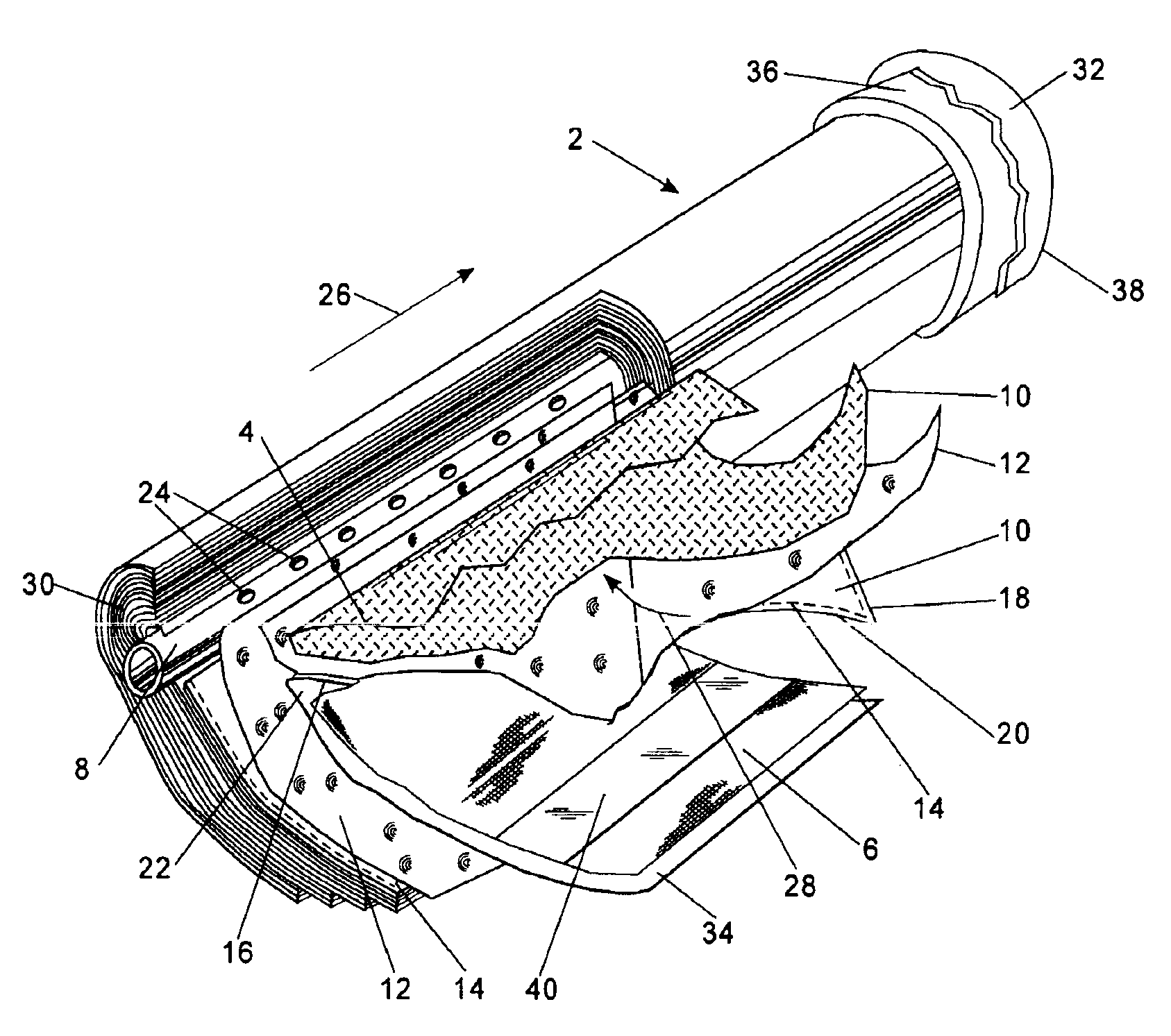
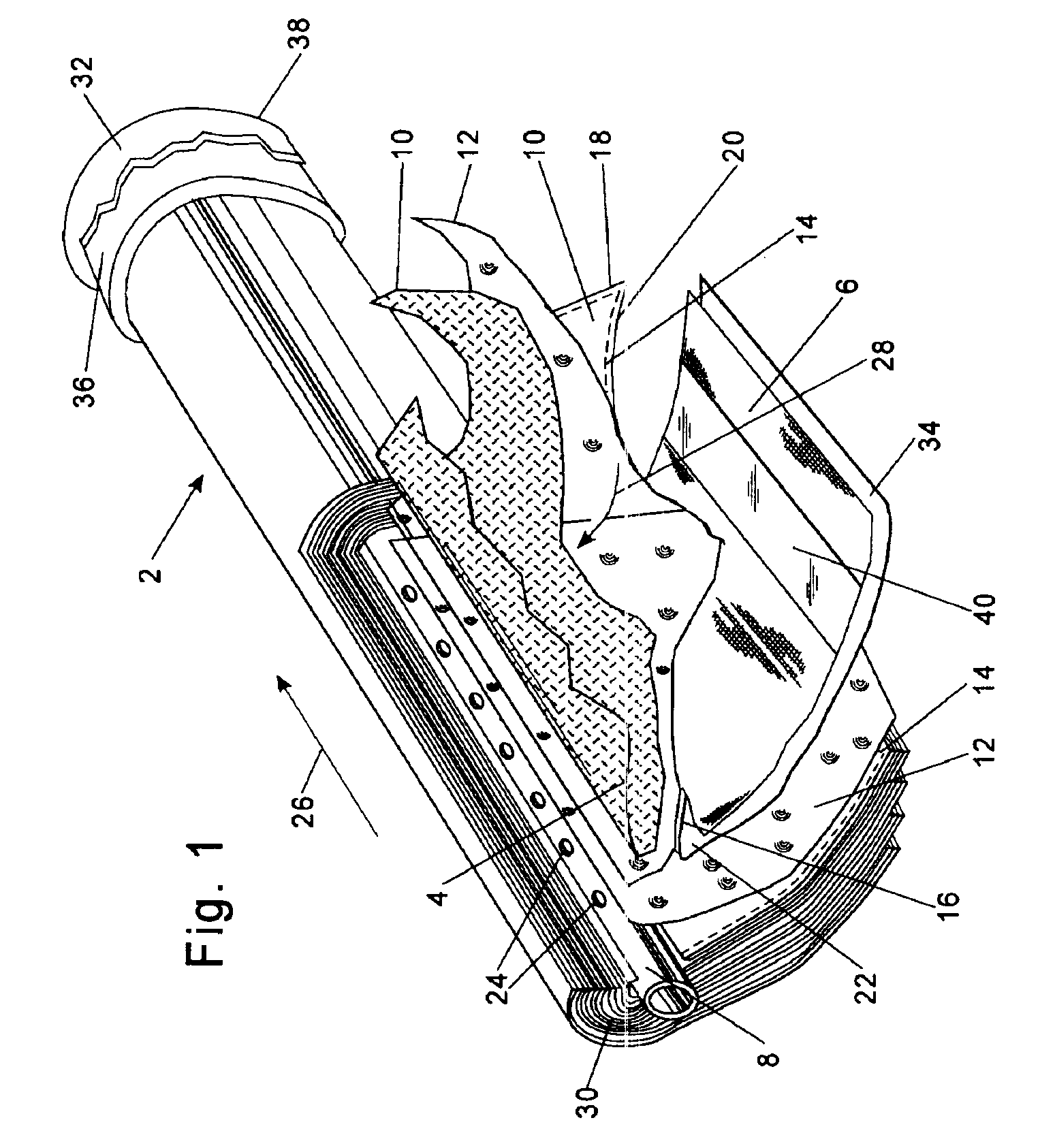
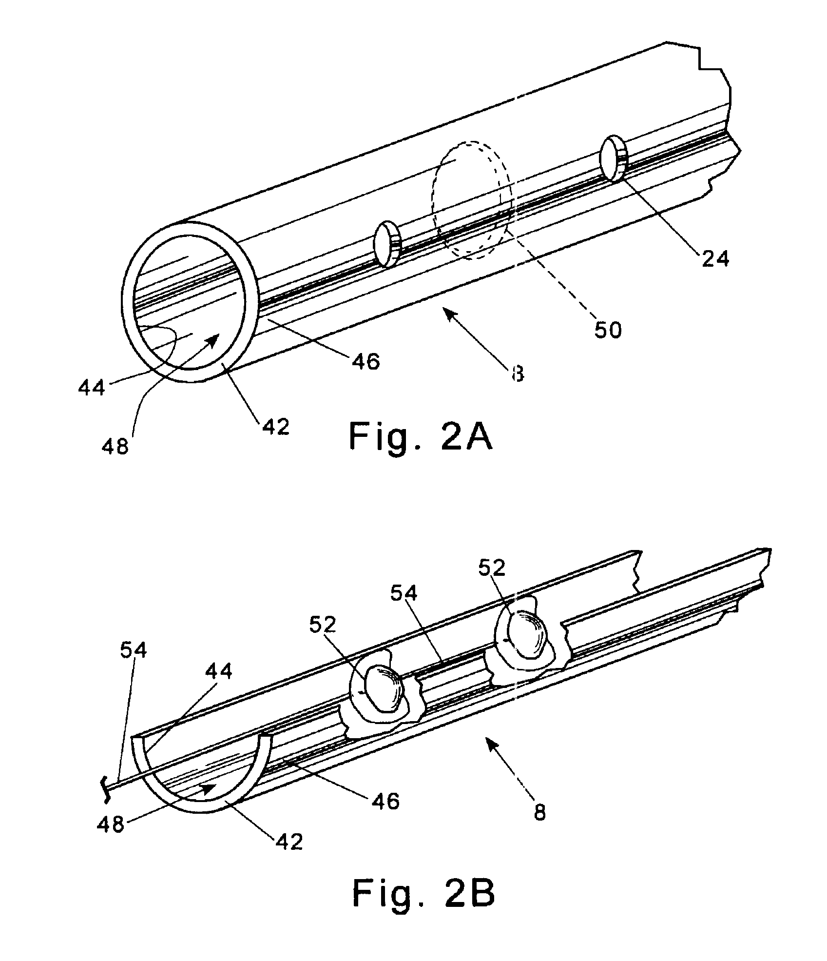
The present invention provides several embodiments for measuring membrane fouling in a spiral wound module. By placing an acoustic transducer near the permeate collection tube, the invention allows for early detection and measurement of membrane fouling. This technology is applicable to a wide range of spiral wound modules and can be used in real-time, on-line monitoring during standard module operation or cleaning. The invention optimizes module performance, maintenance, replacement, and cleaning based on direct measurement of membrane fouling.

Problems solved by technology

Membrane fouling is a common problem in most membrane based separation processes.
Membrane fouling is a chemical phenomenon where solutes are deposited upon the membrane surface resulting in reduced membrane flux and selectivity.
Failure to timely clean membranes can result in higher cleaning costs (e.g. longer cleaning times, additional cleaning agents, use of more aggressive cleaning agents, etc.) and premature module replacement.
Loss of operating time and increased costs associated with membrane cleaning and premature module replacement along with reduced operating performance result in overall increased separation costs.
Spiral wound module configurations present specific challenges with respect to membrane fouling.
Due to their spiral configuration, it is difficult to visually inspect the membrane surface without destroying or otherwise compromising the integrity of the module.
Unfortunately, these indirect measures can be influenced by factors unrelated to membrane fouling, such as concentration polarization.
This latter reference indicates that the application of ultrasound to spiral wound modules is complicated by several factors including a much more complex signal pattern resulting from multiple reflections from the surface layers of multiple layers within spiral wound modules and loss of acoustic information caused by signal attenuation through these multiple layers as well as through the module housing.
That is, the combination of materials having distinct acoustic impedance properties along with many internal interfaces within an integral composite structure makes the interpretation of acoustic signals exceedingly difficult.
As a consequence, the use of acoustic measurements through the outer housing of many spiral wound modules is quite limited.
The use of relatively thicker fiber reinforced plastic housings further minimizes the utility of the aforementioned ultrasonic techniques.
Membrane fouling tends to initiate and be most pronounced in areas experiencing the highest permeate flux, i.e. areas of the membrane envelope adjacent to the permeate collection tube.
Due to limitations of acoustic signal strength and the ever increasing complexity of interpreting reflective signals from multiple interfaces, the aforementioned ultrasound techniques are limited to examining only the outermost membrane layers.
Unfortunately, these outer layers typically include tape and excess permeate and feed spacers as well as glued sections of membrane which are attached to the permeate spacer.

Method used


Image

  • Use of acoustic signals for measuring membrane fouling in spiral wound modules
  • Use of acoustic signals for measuring membrane fouling in spiral wound modules
  • Use of acoustic signals for measuring membrane fouling in spiral wound modules

Examples


examples

[0054]An embodiment of the invention was configured in a manner similar to that shown in FIG. 3 including a single FilmTec BW30XLE-440 spiral wound module positioned within a fiberglass pressure vessel. A removable probe was equipped with a Panametrics immersion transducer model A306S-SU including an acoustic reflector as shown in FIG. 3. The transducer was inserted approximately ten inches into the permeate collection tube of the module. The probe was connected to an Olympus pulser / receiver model 5800PR-15-U-9F12. The pulser / receiving settings were as follows: PRF: 100 Hz; Energy: 100 μJ; Damping: 50 ohms; High Filter: 1 MHz; Low Filter 35 MHz; Input Attenuation: 20 dB; Output Attenuation: 9 dB; Gain: 20 dB. The transducer generated a pulse width of one full cycle at 2.225 MHz in water. The pulse width (50% of the maximum amplitude) in frequency space was from 1.45 to 2.69 MHZ. Municipal tap water (Edina Minn.) was used as feed and the system was operated at approximately fifty per...


PUM

PropertyMeasurementUnit
diameteraaaaaaaaaa
diameteraaaaaaaaaa
diameteraaaaaaaaaa

Abstract

A spiral wound module assembly comprising: a permeate collection tube, at least one membrane envelope wound about the permeate collection tube, an outer module housing, and at least one acoustic transducer located adjacent to the permeate collection tube. Several embodiments are disclosed including a stand-alone probe adapted for insertion into the permeate collection tube. In several other embodiments, one or more transducers are secured to the inner surface of the permeate collection tube. The invention further includes a method of measuring membrane fouling within a spiral wound module comprising the steps of: a) transmitting an acoustic signal from a location adjacent to the permeate collection tube; b) receiving an echo signal resulting from the transmitted acoustic signal reflecting from an interface within the module; c) providing a reference signal corresponding to a known state of membrane fouling; d) comparing the echo signal to the reference signal; and e) determining a state of membrane fouling based upon the comparison of the echo signal and reference signal.

Description

BACKGROUND OF THE INVENTION[0001](1) Field of the Invention[0002]The invention includes an apparatus and method of using acoustic waves (“signals”) to measure membrane fouling within a spiral wound membrane module. In one preferred embodiment, the invention includes a spiral wound module assembly including at least one membrane envelope wound about a permeate collection tube, an outer module housing, and an acoustic transducer located adjacent to the permeate collection tube. Acoustic signals are transmitted and received by the transducer and are compared with a reference signal to determine the state of membrane fouling.[0003](2) Description of the Related Art[0004]Membrane fouling is a common problem in most membrane based separation processes. Membrane fouling is a chemical phenomenon where solutes are deposited upon the membrane surface resulting in reduced membrane flux and selectivity. Failure to timely clean membranes can result in higher cleaning costs (e.g. longer cleaning ...

Claims


Application Information

Patent Timeline
Patent Type & Authority Patents(United States)
IPC IPC(8): G01D7/00B01D35/00
CPCB01D61/12B01D61/22B01D63/10B01D65/10G01N29/041G01N29/4436G01N2291/0258G01N2291/044B01D65/109
Inventor MICKOLS, WILLIAM E.KORELTZ, MICHAEL S.MOLL, DAVID J.STREETER, DONALD B.
Owner DOW GLOBAL TECH LLC
Learn More