
Electroactive polymer actuated cerebrospinal fluid shunt

a cerebrospinal fluid and electroactive technology, applied in the field of electroactive polymer actuated cerebrospinal fluid shunt, can solve the problems of hydrocephalus through the obstruction or excessive production of cerebrospinal fluid in the brain, other dangerous conditions, impaired blood flow, etc., and achieve the effect of reducing the number of mechanical components and reducing the possibility of potential obstruction

Inactive Publication Date: 2012-07-03
ANITEAL LAB
View PDF20 Cites 1 Cited by
  • Summary
  • Abstract
  • Description
  • Claims
  • Application Information

AI Technical Summary

Benefits of technology

"The present invention provides an implantable shunt system that uses an electroactive polymer actuated valve to control and regulate the flow of cerebrospinal fluid (CSF) from the brain ventricle to a secondary cavity in the body. The electroactive polymer actuated valve can also act as a sensor for pressure changes within the shunt system. The invention has several advantages, including the use of a single actuating element for both adjusting the valve threshold pressure and sensing pressure, the elimination of the need for multiple mechanical components, and the potential to decrease the possibility of valve obstruction. The electroactive polymer actuated valve can also be regulated by an external control unit."

Problems solved by technology

The abnormal accumulation of CSF in the brain ventricles consequently leads to the condition of hydrocephalus through the obstruction or excessive production of CSF in the brain.
If left untreated, hydrocephalus can lead to other dangerous conditions, including subdural hematoma, impaired blood flow, coma, or even the eventual death of a patient.
Although many of the existing shunt systems have been implemented with successful results, they can still present problems given certain circumstances.
A primary example of an essential problem that has existed within the use of typical shunt systems is in the inability to adjust the threshold pressure within the shunt valve.
This is essential because if the valve pressure is not adjusted, it could lead to the overdrainage of CSF from the brain ventricle or the accumulation of CSF within the ventricles resulting in an elevated ICP.
Although this has provided an important solution to some of the most essential problems associated with shunts, existing shunt systems in general still do not have the ability to adjust threshold pressures autonomously in accordance with the constantly changing physiological constraints of a patient which inevitably change over time.
These patents all discuss a variety of different methods, but there are also many limitations to the methods presented due to how the sensor and actuating elements effectively adjust the threshold pressure.
These limitations are often a result of the particular means for actuation, such as the constant reliability to an electromagnetic actuator.
The implementation of existing magnetically actuated shunt valves also do not provide a means for a sensing element that is directly coupled to the means for actuation, which can also be improved upon through the use of alternative actuation methods.
The problems that can be improved upon concern not only the ability to have an automatically adjustable pressure valve, which is also externally programmable, but also including the detection of pressures that exist within the implanted shunt assembly which can be communicated to an external point outside of the patient's body.

Method used


Image

  • Electroactive polymer actuated cerebrospinal fluid shunt
  • Electroactive polymer actuated cerebrospinal fluid shunt
  • Electroactive polymer actuated cerebrospinal fluid shunt

Examples


Embodiment Construction

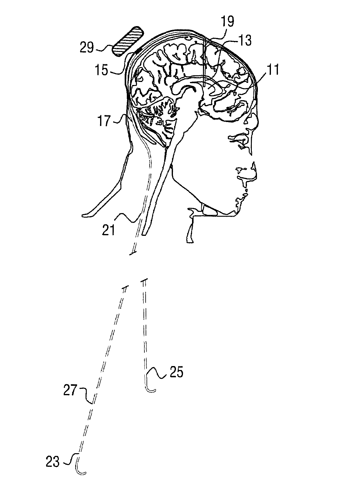
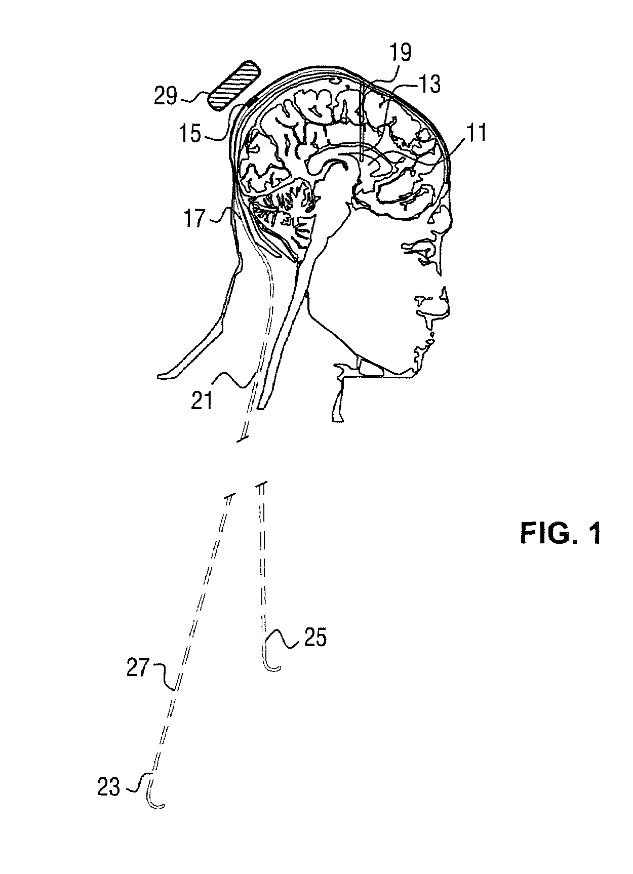
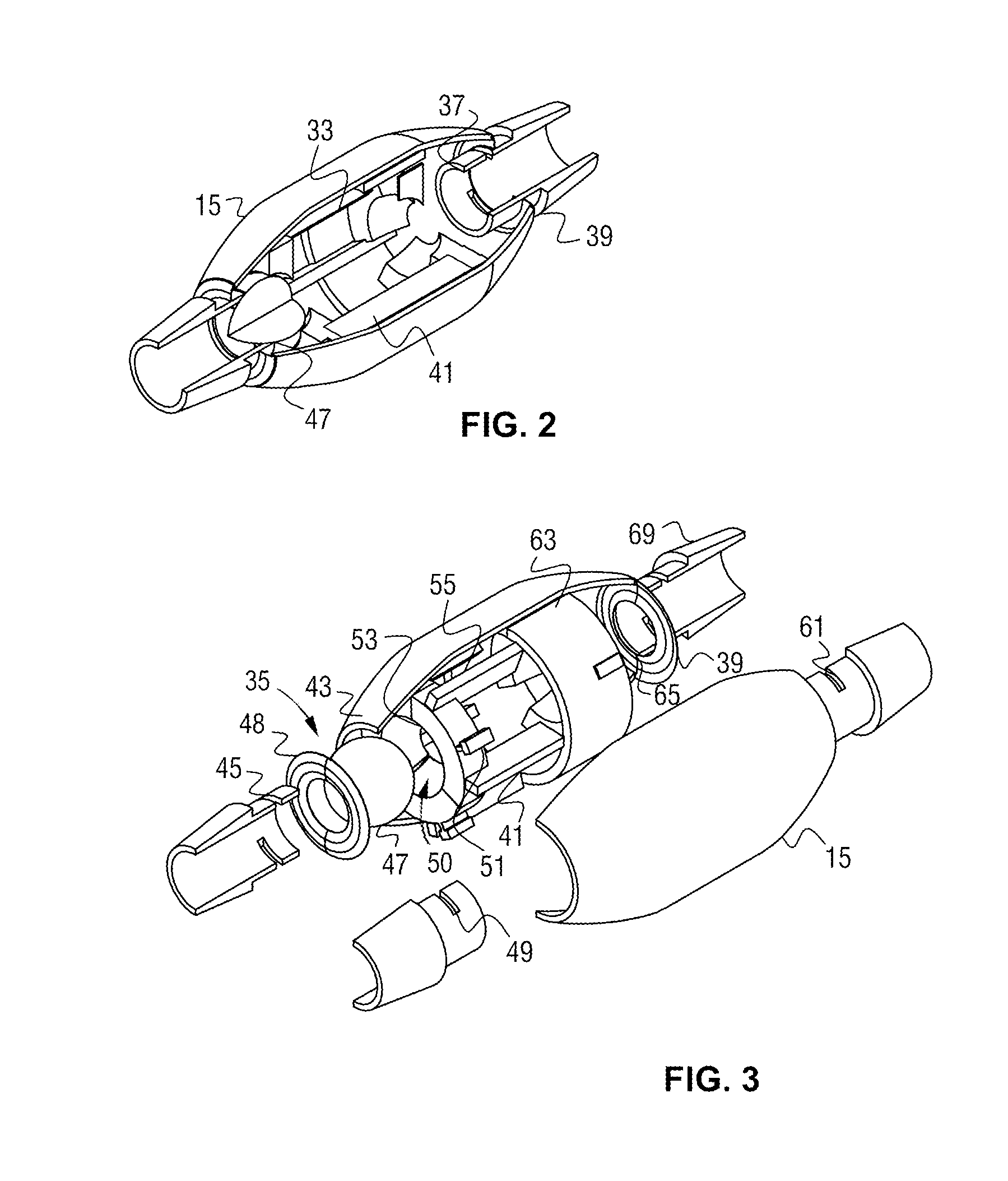
[0027]In the embodiment present in FIG. 1, a typical cerebrospinal fluid (CSF) shunt is shown with all of its essential elements and how they are implanted within a patient's body. The electroactive polymer actuated shunt valve 15 is located at a point underneath the scalp of a patient which is coupled to a ventricular catheter 19 that is inserted into the brain ventricle 11. The ventricular catheter 19 receives CSF from its distal end 13 which flows to the electroactive polymer actuated shunt valve 15. The control and regulation of the flow of CSF is ultimately defined by a predetermined threshold pressure which can ultimately be adjusted through the external control unit 29, which is placed directly over the scalp protrusion where the shunt valve 15 is located. Once the threshold pressure is defined and / or continuously adjusted based upon pressure levels read by an electroactive polymer transducer, or a sensor also coupled to the shunt valve 15, the valve redirects the CSF to a di...


PUM


Abstract

A cerebrospinal fluid (CSF) shunt comprises a ventricular catheter and an electroactive polymer actuated valve for regulating the drainage rate of CSF from the brain ventricle of a patient. The shunt system also comprises a distal catheter for discharge of the CSF to a separate location in the patient's body such as the peritoneal cavity or atrium of the heart. The electroactive polymer actuated valve regulates the flow rate of CSF through a predetermined threshold pressure, which can be adjusted and programmed externally from the patient's body by means of an external control unit signal, as well as through a signal indicated by an internal sensor or an electroactive polymer transducer. The sensor also communicates a signal to the external control unit for indicating the internal pressure at a single location or multiple locations throughout the fully implanted shunt assembly.

Description

CROSS-REFERENCE TO RELATED APPLICATIONS[0001]This application claims the benefit of the filing date of provisional application No. 60 / 846,952, filed Sep. 24, 2006.FIELD OF THE INVENTION[0002]The present invention relates to shunt systems and methods for removing or draining cerebrospinal fluid from the brain ventricle of a patient to control intracranial pressure for the treatment of hydrocephalus and other diseases.BACKGROUND OF THE INVENTION[0003]Cerebrospinal fluid (CSF) is a clear bodily fluid that is primarily produced by the choroid plexus and continuously circulates throughout the ventricular system of the brain and around the spinal cord. The essential function of CSF is to provide a protective cushion to the brain and spinal cord in that it acts as a shock absorber by keeping the brain and spinal cord buoyant, which ultimately can prevent injuries to the central nervous system.[0004]The abnormal accumulation of CSF in the brain ventricles consequently leads to the condition...

Claims


Application Information

Patent Timeline
Patent Type & Authority Patents(United States)
IPC IPC(8): A61M5/00
CPCA61B5/031A61M27/006A61M2205/0283
Inventor DELAPORTE, STEPHEN E.
Owner ANITEAL LAB
Learn More