Spatially smart optical sensing and scanning

a scanning and optical sensing technology, applied in the field of optical sensors, can solve the problems of poor spatial resolution of images and much effort spent on extracting target axial direction data, and achieve the effect of spatial intelligen

Inactive Publication Date: 2012-07-03
UNIV OF CENT FLORIDA RES FOUND INC +2
View PDF19 Cites 65 Cited by
  • Summary
  • Abstract
  • Description
  • Claims
  • Application Information

AI Technical Summary

Benefits of technology

[0017]Another objective of the invention is to provide devices, methods and optical sensor designs wherein spatial smartness is produced by matching the transverse dimensions of the sampling optical beam to the transverse size of the flat target zone for a given axial (along light travel direction) target distance. In effect, instantaneous spatial mapping of the flat target zone, like an optical chip for thermal sensing, is implemented without the need for point-by-point smallest resolution transverse beam scanning over the flat zone.
[0018]Thus, compared to prior-art optical distance measurement 3-D sensors where the scanning beam spot size stays fixed (apart from the natural beam diffraction-based expansion) for all 3-D scan positions of the beam on the 3-D target (what is called non-sma

Problems solved by technology

As described in the prior art, much effort is spent to extract the target axial direction data such as via optical triangulation methods.
A problem with all prior-art laser scanning projection displays is that the farther the dist

Method used


Image

  • Spatially smart optical sensing and scanning
  • Spatially smart optical sensing and scanning
  • Spatially smart optical sensing and scanning

Examples


first embodiment

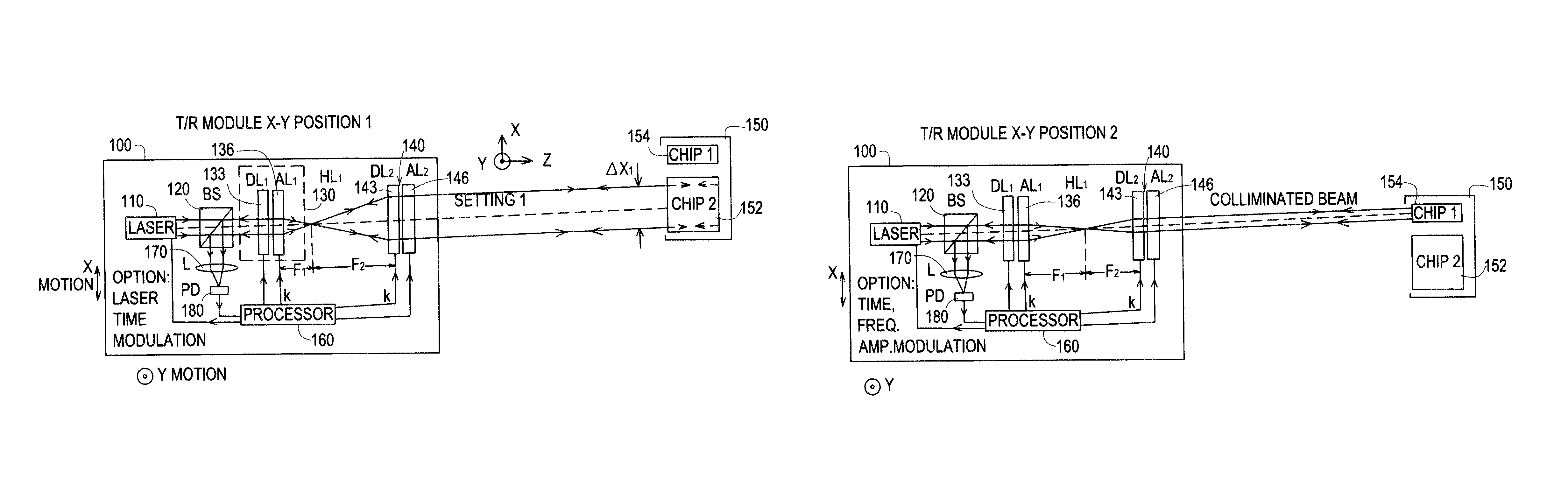
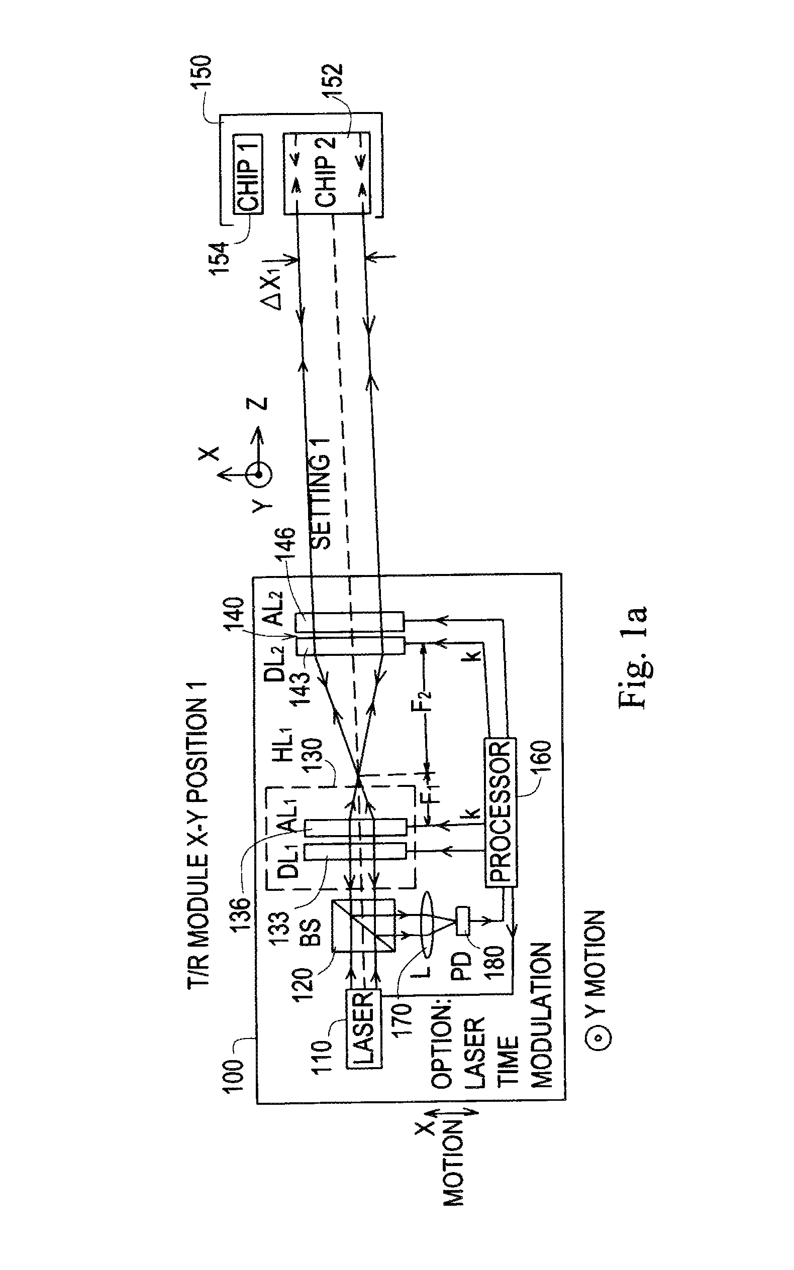
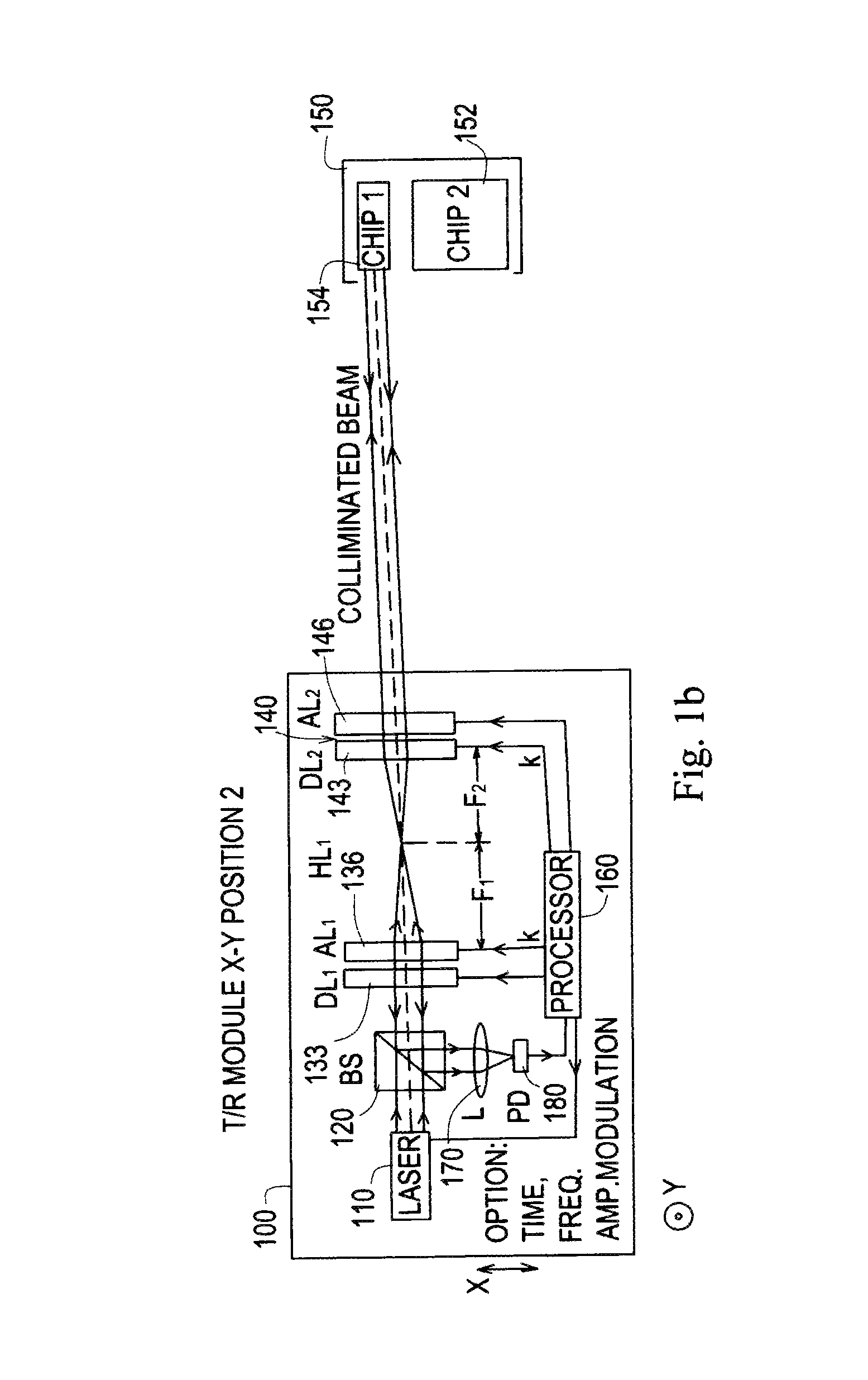
[0079]In summary, a first embodiment provides a smart spatial optical sampling / sensing device that includes a laser source for producing an input laser beam, a variable focal length telescopic targeting system to project the input laser beam toward a target subjected to a measurement, a detection device for detecting the return beam from the target and generating a signal in response, and a processing device to control the laser source and variable focal length telescopic targeting system and receive the signal from the detection device, wherein the optical distance sensor adjusts the transverse beam spot size at each axial position based on the specific target's 3-D shape profile for an optimized smaller sampling data set is generated for a given target.

[0080]The variable focal length optical device includes a beam splitter, and a first variable hybrid lens to produces a F1 effective focal length cascaded with a second variable hybrid lens to produces a F1 effective focal length se...

third embodiment

[0083]A third embodiment provides a laser scanning display system that includes a controllable laser source to produce a laser beam, a wavelength beam forming optics for receiving the laser beam and producing a scanning beam, a programmable hybrid lens to focus the scanning beam, an adjustable scanning mirror for reflecting the focused scanning beam toward the display screen, a processing device having a memory to control the laser source, to control the wavelength beam forming optics, to focus the scanning beam spot in the display screen, to adjust a position of the adjustable scanning mirror to scan the display screen and to record the programmable hybrid lens focal length and mirror scan angles in the memory to generate plural pixels on the display screen, and a display screen to display an image produced by scanning the display screen with the reflected focused scanning beam. The controllable laser source can be a first, second and third laser source each producing a different c...


PUM


Abstract

Methods, devices and systems of an optical sensor for spatially smart 3-D object measurements using variable focal length lenses to target both specular and diffuse objects by matching transverse dimensions of the sampling optical beam to the transverse size of the flat target for given axial target distance for instantaneous spatial mapping of flat target, zone. The sensor allows volumetric data compressed remote sensing of object transverse dimensions including cross-sectional size, motion transverse displacement, inter-objects transverse gap distance, 3-D animation data acquisition, laser-based 3-D machining, and 3-D inspection and testing. An embodiment provides a 2-D optical display using 2-D laser scanning and 3-D beamforming optics engaged with sensor optics to measure distance of display screen from the laser source and scanning optics by adjusting its focus to produce the smallest focused beam spot on the display screen. With known screen distance, the angular scan range for the scan mirrors can be computed to generate the number of scanned spots in the 2-D display.

Description

[0001]This application claims the benefit of priority to U.S. Provisional Application Nos. 61 / 157,448 filed on Mar. 4, 2009 and 61 / 169,501 filed on Apr. 15, 2009.FIELD OF THE INVENTION[0002]This invention relates to optical sensors and, in particular, to methods and devices and systems of optical sensor designs for spatially smart three dimensional object measurements using hybrid digital-analog controlled variable focal length lenses to target specular and diffuse objects and laser scanning displays where a laser beam is scanned in 2-D space by scanning optics so the human eye on temporal integration in-directly sees a 2-D image on the projection screen or directly on the human retina.BACKGROUND AND PRIOR ART[0003]Three-dimensional (3-D) object sensing is required in a variety of industrial and scientific applications such as thermal sensing, animation, laser machining, parts inspection, virtual reality, building scanning, and architecture and model construction. Target 3-D informa...

Claims


Application Information

Patent Timeline
IPC IPC(8): G01B11/30
CPCG01B11/026G01B11/24G01S17/89G01S7/4814
Inventor RIZA, NABEEL A.PEREZ, FRANK
Owner UNIV OF CENT FLORIDA RES FOUND INC
Why Eureka
Try Eureka