
Plasma generator and method of generating plasma using the same

a plasma generator and plasma technology, applied in the direction of nitrogen oxide/oxyacid, gas-gas reaction process, nitric oxide, etc., can solve the problems of increasing the cost of the whole apparatus, increasing the cost, and increasing the complexity of the entire apparatus, so as to prevent the impedance from changing, the energy required for igniting plasma is lower, and the plasma is stable.

Inactive Publication Date: 2012-07-10
UNIVERSITY OF THE RYUKYUS
View PDF30 Cites 17 Cited by
  • Summary
  • Abstract
  • Description
  • Claims
  • Application Information

AI Technical Summary

Benefits of technology

"The present invention provides a plasma generator with improved ignition of plasma and reduced impact of the cavity on the ignition. The generator includes a non-conductive gas flow pipe and a conductive antenna pipe. The antenna pipe surrounds the gas flow pipe and is irradiated with microwaves to convert the gas to plasma. A slit is created in the antenna pipe, which can be a straight slit or a bent slit. The length of the slit can be a multiple of the half wavelength of microwaves. The plasma generator can have one or more gas flow pipes with an antenna pipe. The plasma generator can be used in a method for generating plasma by keeping the air pressure lower than ambient pressure and igniting plasma through irradiation with microwaves. The method can also involve supplying a first gas for ignition and a second gas that is more difficult to convert to plasma. The plasma generator can be moved relative to each other after ignition to improve the plasma generation. The invention provides a more efficient and reliable plasma generator for various applications."

Problems solved by technology

The possibility of electrons and ions generated between electrodes colliding with the electrodes so that the electrodes become of a high temperature and wear out, as well as the possibility of part of the metal material forming the electrodes being released into the plasma so that an impurity gets mixed in with the plasma can be cited as being a problem with arc discharge.
Therefore, a mechanism for adjusting the frequency is required, making the entire apparatus complicated and raising the cost.
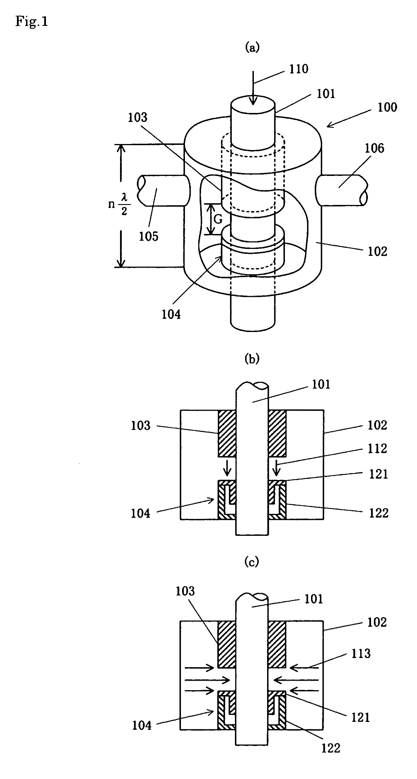
In addition, in the case where a method for minimizing the change in the impedance by changing the form of the cavity 102 is adopted (here, Patent Document 2 does not disclose any concrete configuration), the form of the cavity 102 is limited, and it becomes difficult to flexibly cope with various changes, for example when a number of quartz pipes are provided.

Method used


Image

  • Plasma generator and method of generating plasma using the same
  • Plasma generator and method of generating plasma using the same
  • Plasma generator and method of generating plasma using the same

Examples


example 1

[0165]The results of the experiments using the plasma generator according to the present invention are described below.

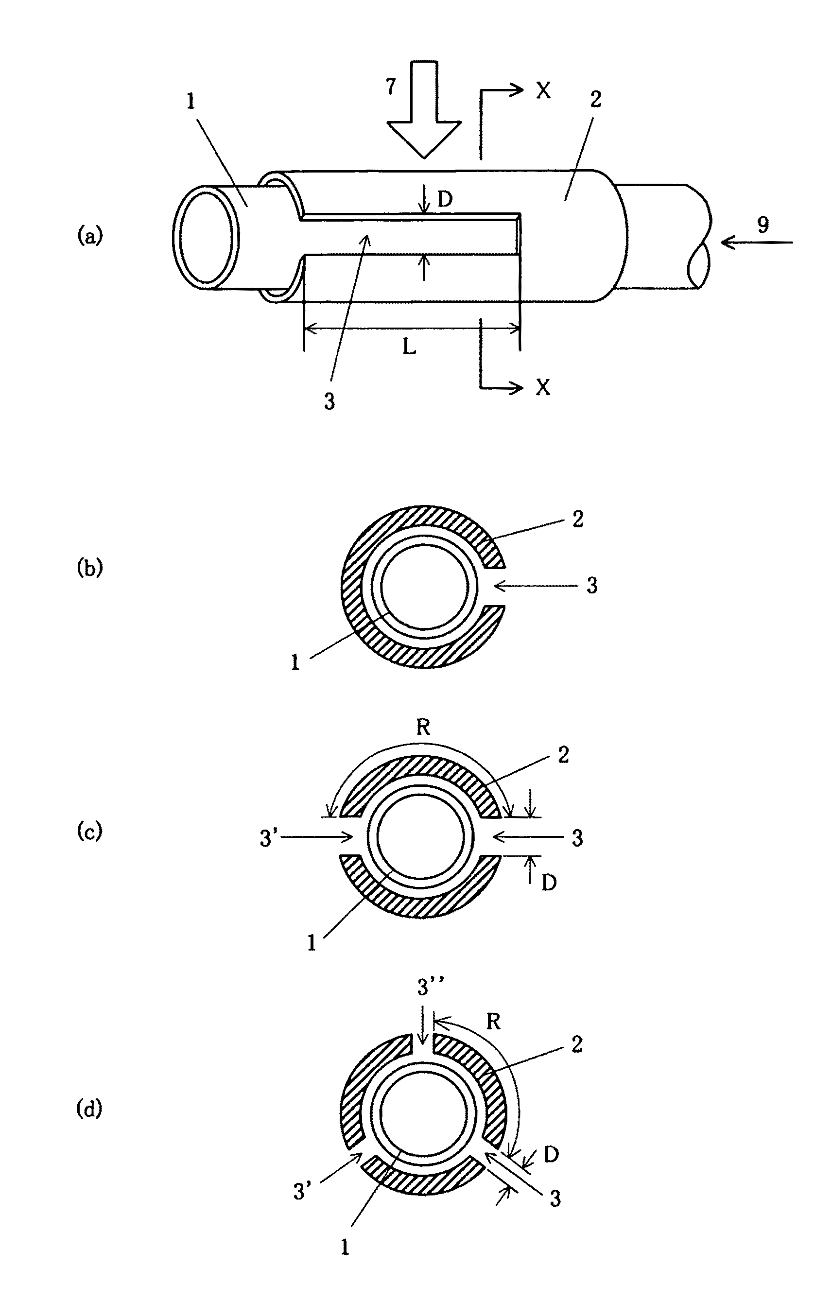
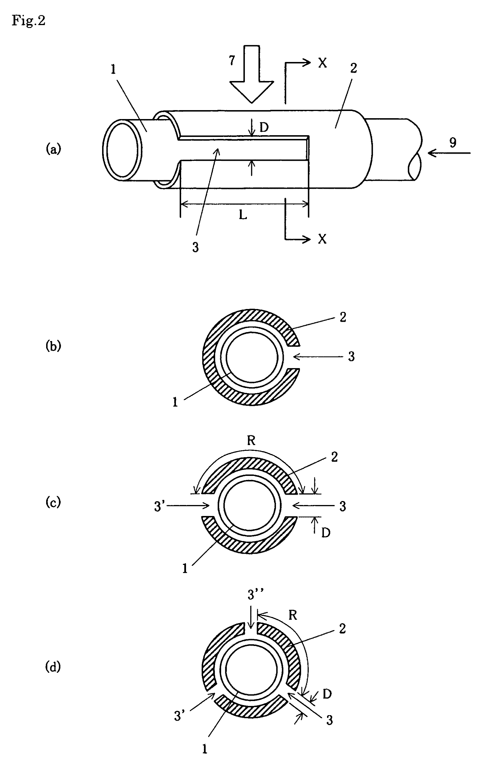
[0166]In the plasma generating portion shown in FIGS. 2(a) to 2(d), a quartz pipe (inner diameter: 20 mm, outer diameter: 22 mm) was used as the gas flow pipe and a pipe made of aluminum (inner diameter: 26 mm, outer diameter: 28 mm) was used as the antenna pipe. A slit having a depth D of 5 mm and a length L of 60 mm was created in the antenna pipe.

[0167]The plasma generating portion made up of the antenna pipe and the gas flow pipe was placed inside a chamber having an inner diameter of 160 mm and a length of 1500 mm, which was the shielding means.

[0168]The pressure inside the gas flow pipe was reduced to 102 Pa, and at the same time, an argon gas was introduced into the gas flow pipe at a gas flow rate of 10 (l / min), and furthermore, microwaves (frequency: 2.45 GHz) with a power of 600 W for introducing microwaves were introduced into the chamber.

[0169]The inside...

example 2

[0170]Next, the plasma generator shown in FIG. 17 was used for experiments.

[0171]The plasma generator can be roughly divided into two portions where one was a plasma production chamber and the other was a process chamber. It becomes possible to irradiate various objects with radicals by providing a process chamber. The inside of the plasma production chamber was partitioned with shield plates made of aluminum, and the quartz pipe (inner diameter: 10 mm, outer diameter: 30 mm) passed through the center axis so as to extend into the process chamber. Furthermore, the quartz pipe was covered with a cylindrical antenna made of aluminum, and two slits having a length of 60 mm, which corresponds to the half wavelength of the microwaves (width: 5 mm), were provided to the antenna in symmetrical locations (see FIG. 2(c)), and one of these was placed so as to be directed to the inlet for microwaves.

[0172]According to an example of the method for generating plasma, air is discharged from insid...

example 3

[0179]Next, experiments were conducted using the plasma generator shown in FIG. 21.

[0180]The plasma generator was formed of a process chamber made of stainless steel having an inner diameter of 160 mm and a length of 340 mm, and a waveguide made of aluminum having an inner surface with a height of 54 mm and a width of 109 mm. A quartz pipe having an inner diameter of 6 mm (outer diameter: 8 mm) which penetrates through the waveguide was connected to the process chamber and covered with an antenna having an outer diameter of 12 mm and an inner diameter of 10 mm with two slits. FIG. 22 is a cross sectional diagram showing the relationship between the antenna pipe and the waveguide.

[0181]A plunger (aluminum plate) for adjusting the distribution of the electrical field of microwaves was provided inside the waveguide, and the position of the plunger could be adjusted with a plunger position adjusting rod.

[0182]In the plasma generator in FIG. 21, plasma is generated through the following ...


PUM

PropertyMeasurementUnit
lengthaaaaaaaaaa
lengthaaaaaaaaaa
pressureaaaaaaaaaa

Abstract

A plasma generator in which the variation of the impedance in the cavity before and after plasma is ignited is less and hardly affected by the shape of the cavity, and the ignitability of the plasma is improved and a method of generating plasma using the plasma generator are provided. The plasma generator comprises a nonconductive gas flow pipe (1) for introducing a gas (9) for generating plasma and discharging it into the atmosphere and a conductive antenna pipe (2) surrounding the gas flow pipe. A microwave (7) is applied to the antenna pipe to change the gas in the gas flow pipe into plasma. The plasma generator is characterized in that a slit (3) with a predetermined length is formed in the antenna pipe (2) along the axial direction of the gas flow pipe. Preferably, the plasma generator is characterized in that the length of the slit is an integral multiple of the half-wave length of the applied microwave.

Description

TECHNICAL FIELD[0001]This invention relates to a plasma generator and a method for generating plasma using the same, and in particular, to a plasma generator which makes it possible to generate plasma using microwaves in the air and a method for generating plasma using the same.BACKGROUND ART[0002]Plasma generated in the air is conventionally used in various industrial fields, such as those dealing with welding of materials having a high melting point, surface cleaning in processes for semiconductor manufacture, improvement of the surface of metal materials and the like, and generation of fine particles. In addition, the application of plasma under ambient pressure has been expanding rapidly, so that plasma is now used in sterilizing processes for medical instruments.[0003]As examples of a method for generating plasma under ambient pressure, generation of plasma using arc discharge and a method for heating a gas using microwaves can be cited.[0004]Patent Document 1 discloses a metho...

Claims


Application Information

Patent Timeline
Patent Type & Authority Patents(United States)
IPC IPC(8): A62D3/178B01J19/08C25B5/00B01J19/12C23C16/50C23C16/511
CPCH01J37/32192H05H1/24H05H1/46H05H1/463
Inventor YONESU, AKIRA
Owner UNIVERSITY OF THE RYUKYUS
Learn More