Timing error detector and method thereof

a timing error and detector technology, applied in the field of timing error detectors, can solve the problems of large jitter, non-linear effect, receiver side cannot recover information transmitted from the transmitter side, etc., and achieve the effect of reducing the peak-to-peak jitter of the recovered clock pulse, enhancing the timing error detection gain, and improving the quality of the received signal

Active Publication Date: 2012-07-10
NAT TAIWAN UNIV
View PDF7 Cites 8 Cited by
  • Summary
  • Abstract
  • Description
  • Claims
  • Application Information

AI Technical Summary

Benefits of technology

[0009]A primary objective of the present invention is to provide a timing error detector, adapted for a non-linear Tomlinson-Harashima precoder of a transmitter in a baseband communication system, e.g., a 10 GBASE-T system, for extracting correct timing error information from the received signals. In accordance with the present invention, an autocorrelation between effective data sequences (EDS) is constructed, and a mean square error (MSE) between the received and the desired EDS, thus reducing the peak-to-peak jitter of the recovered clock pulse and enhancing the timing error detection gain, and further improving the quality of the received signals at the input of slicers and reducing the error rate thereof.
[0010]Another primary objective of the present invention is to provide a method for detecting a timing error, for incorporating with a non-linear Tomlinson-Harashima precoder of a baseband transmitter, and extracting the correct timing error information according to the timing error instant estimation value signals, so as to bypass the non-linear effect caused by the Tomlinson-Harashima precoder, thus improving the signal-to-noise ratio at the input of the slicer.

Problems solved by technology

In a transmission channel of a high speed digital transmission system, there are many unavoidable noise sources, which provide noises interfering clock signals recovered by the receiver side.
Such noise interferences may cause large jitters, and therefore the receiver side cannot recover information transmitted from the transmitter side.
In a THP of a baseband transmitter, the THP employs a modular element for restricting the output within a predetermined range, which causes a non-linear effect, and therefore the MM-TED of the baseband communication system using the DFE cannot detect the correct timing error information.
Secondly, the estimated timing error is related to the algorithm for dynamically adjusting the FFE coefficient, and accordingly different estimated values of the timing error may be obtained in accordance with different adaptive algorithms.

Method used


Image

  • Timing error detector and method thereof
  • Timing error detector and method thereof
  • Timing error detector and method thereof

Examples


Embodiment Construction

[0017]The accompanying drawings are included to provide a further understanding of the invention, and are incorporated in and constitute a part of this specification. The drawings illustrate embodiments of the invention and, together with the description, serve to explain the principles of the invention.

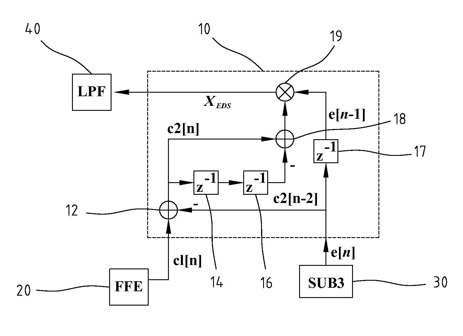
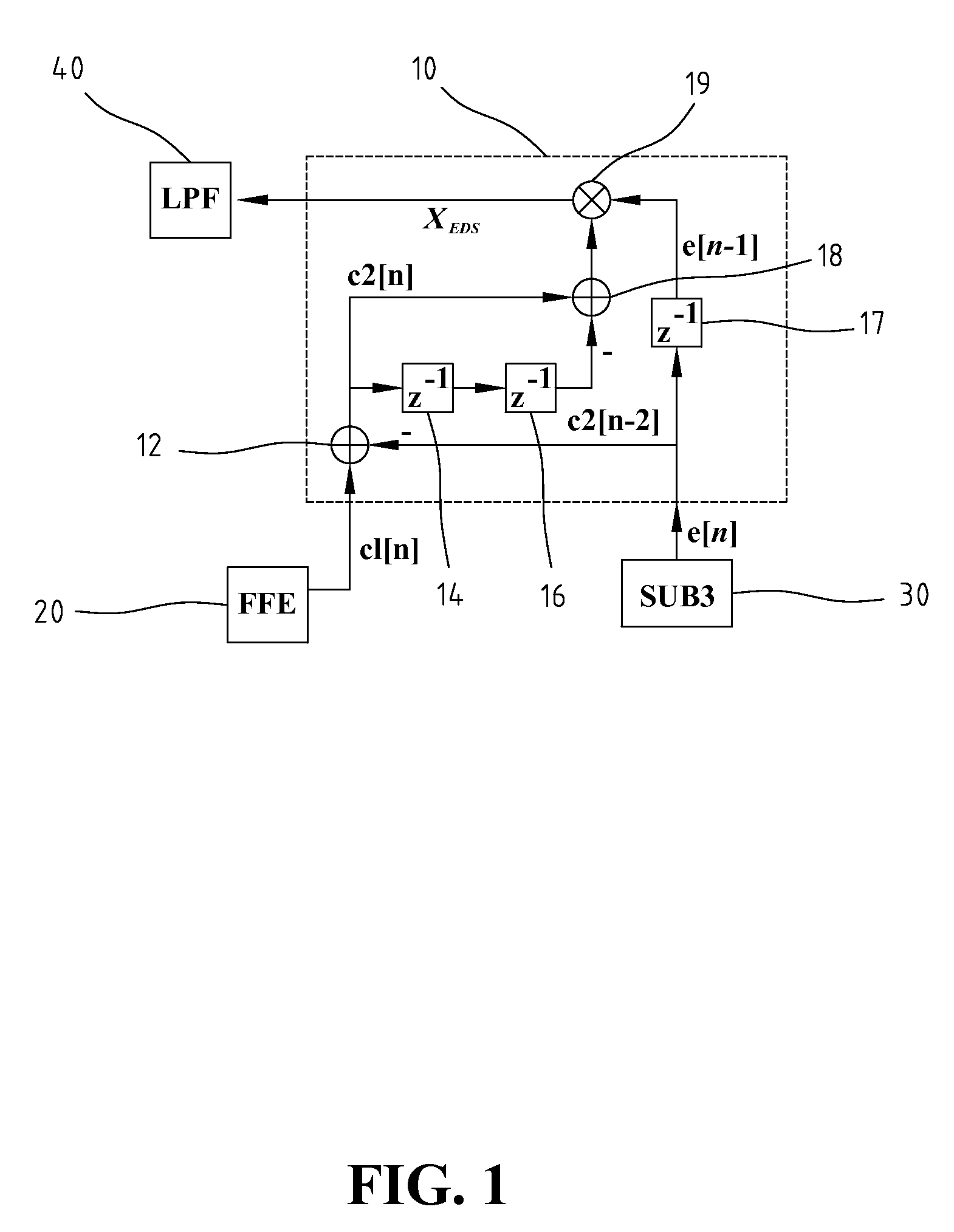
[0018]FIG. 1 is a schematic diagram illustrating an effective data sequence based timing error detection (EDS-TED) 10 according to an embodiment of the present invention. Referring to FIG. 1, the EDS-TED 10 includes a first subtractor 12, a first delayer 14, a second delayer 16, a third delayer 17, a second subtractor 18, and a multiplier 19. The EDS-TED 10 is adapted for processing an EDS c1[n] of the receiver side and an error signal e[n], and generating an output value XEDS. The EDS c1[n] of the receiver side is provided from a feedforward equalizer (FFE) 20, and the error signal e[n] is provided by a posterior subtractor 30. The output value XEDS is received by a loop filter (LPF...


PUM


Abstract

An effective data sequence based timing error detector (EDS-TED) for baseband transmission system using Tomlinson-Harashima Precoder is disclosed. The EDS-TED extracts timing error information embedded in the received signal to build up autocorrelation between the ESD signals and minimize the mean square error between the received and desired EDS so as to improve the performance of the TED in terms of Peak-to-Peak Jitter and TED gain. Thus the quality of the received signal increases and the error rate decreases.

Description

BACKGROUND OF THE INVENTION[0001]1. Field of the Invention[0002]The present invention relates generally to a timing error detector and a method thereof, and more particularly, to a timing error detector for a baseband transmission system using a Tomlinson-Harashima precoder.[0003]2. The Prior Arts[0004]In a transmission channel of a high speed digital transmission system, there are many unavoidable noise sources, which provide noises interfering clock signals recovered by the receiver side. Such noise interferences may cause large jitters, and therefore the receiver side cannot recover information transmitted from the transmitter side. As such, correct timing error information is very important for a high speed digital transmission system, such as a 10 GBASE-T baseband transmission system. Accordingly, an effective technology of extracting the timing error information is very much desired by a receiver, for overcoming the problem caused by the noise contained in the correct timing e...

Claims


Application Information

Patent Timeline
Patent Type & Authority Patents(United States)
IPC IPC(8): H04B3/46
CPCH04L7/0062H04L27/2647
Inventor CHIEN, YING-RENTSAO, HEN-WAI
Owner NAT TAIWAN UNIV
Why Eureka
Try Eureka