
Recursive image quality enhancement on super resolution video

a super-resolution video and image quality technology, applied in the field of super-resolution image processing, can solve the problems of high-cost solution, unsuitable for all applications, and magnifying noise problems, so as to reduce high-frequency noise, enhance the quality of super-resolution video, and suppress ringing artifacts

Active Publication Date: 2012-07-31
SONY CORP +1
View PDF12 Cites 4 Cited by
  • Summary
  • Abstract
  • Description
  • Claims
  • Application Information

AI Technical Summary

Benefits of technology

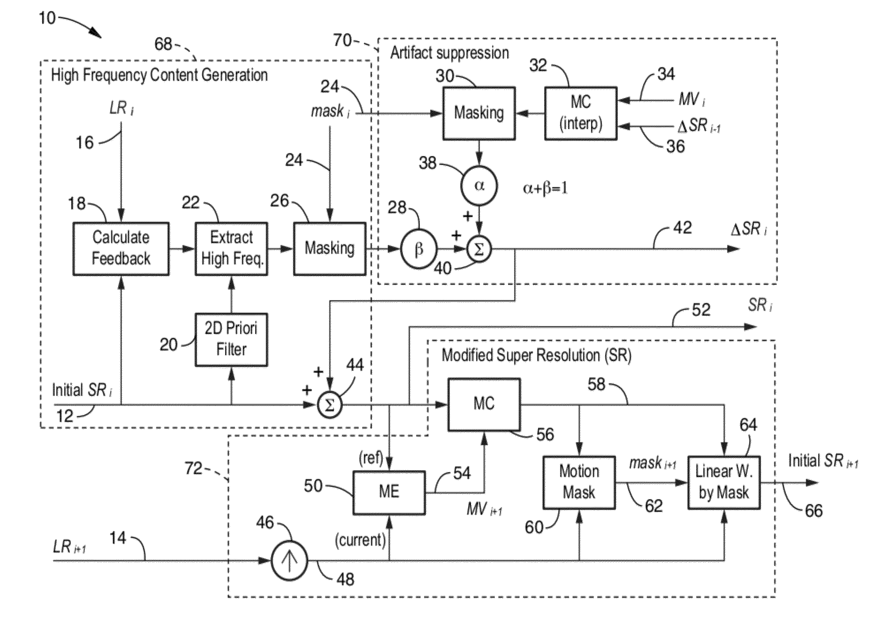
[0013]The method and apparatus of the invention is directed at enhancing the quality of super-resolution video by suppressing ringing artifacts, reducing high-frequency noise, reducing blocking artifacts, and smoothing out the jagged edges of images. Toward fulfilling these objectives the inventive method and apparatus executes mechanisms for smoothing out the high-frequency feedback through a temporal plane, and adaptively applying weighted averaging on current image feedback and smoothed motion compensated feedback.
[0014]It should be recognized that conventional super-resolution approaches improve picture quality by blending a number of images captured with the same scene to estimate missing high frequency components and add them back to the target image. This process needs to be iteratively performed until the feedback converges to a pre-set criterion to achieve a desired quality level. Whereas conventional techniques involve iteratively improving picture quality of a single image by utilizing many images, the real-time applications of the present invention utilize multiple (e.g., two or more) temporally displaced images, preferably sequential frames, for each process and the estimated high-frequency components are updated for quality improvement through time.
[0023]One embodiment of the invention is a method of generating super-resolution imaging, comprising: (a) estimating motion MVi+1 for a super-resolution image SRi as a reference and a low-resolution image LRi+1 at a current temporal position within a series of images i=0, 1, . . . N; (b) generating a motion compensated image on the super-resolution image SRi and constructing an initial super-resolution image initial SRi+1; (c) generating a control parameter (Beta) β in response to motion compensation of an initial SRi input in response to input of a low-resolution image LRi to create recursive high-frequency component feedback; (d) generating a control parameter (alpha) α in response to interpretation of previous estimated high-frequency components ΔSRi−1 and motion estimation MVi; (e) adaptively adjusting the α value in response to motion accuracy; and (f) summing signal α and signal β to output an estimated high-frequency components ΔSRi. Utilization of this method enhances the quality of super-resolution video by suppressing ringing artifacts, reducing high-frequency noise, reducing blocking artifacts, and smoothing out the jagged edges of images.
[0031]An aspect of the invention provides improved image output from improved super-resolution (SR) processing.
[0033]Another aspect of the invention is that of reducing high-frequency noise in response to improved SR image processing.
[0035]Another aspect of the invention is that of reducing the appearance of jagged edges on image subjects of improved SR processing.

Problems solved by technology

It will be recognized that although this produces a desirable video output stream with a minimum of artifacts, it represents a high-cost solution which is not suitable for all applications.
In creating the higher-definition images, noise in the form of high frequency artifacts, are often introduced into the video, while ringing artifacts often appear which magnify the noise problems.
However, such processing is not practical for use in real-time applications or super-resolution video generation.

Method used


Image

  • Recursive image quality enhancement on super resolution video
  • Recursive image quality enhancement on super resolution video
  • Recursive image quality enhancement on super resolution video

Examples


Embodiment Construction

[0052]Referring more specifically to the drawings, for illustrative purposes the present invention is embodied in the apparatus generally shown in FIG. 1, FIG. 3A-3C, FIG. 5A-5B, FIG. 7A-7B and FIG. 8. It will be appreciated that the apparatus may vary as to configuration and as to details of the parts, and that the method may vary as to the specific steps and sequence, without departing from the basic concepts as disclosed herein.

[0053]The inventive apparatus and method generates higher resolution video frames with fewer artifacts and ringing than provided by conventional super-resolution techniques. The invention is preferably implemented as programming executable on a computer, or at least one computer-processing element, configured for processing video streams and executing video algorithms. The invention can also be embodied as an apparatus, or as a media containing programming executable on a computer, and so forth and combinations thereof.

[0054]FIG. 1 illustrates an example o...


PUM


Abstract

Method and apparatus for improving the quality of super-resolution video imaging by suppressing ringing artifacts, reducing high-frequency noise, reducing blocking artifacts, and smoothing out jagged edges of the image to generate pictures that appear cleaner with less edge degradation. The method operates in a recursive manner within a sequence of low resolution images. Conventional SR processing is primarily enhanced within the invention by adding an artifact suppression section which creates a high frequency component signal ΔSRi having significantly reduced artifacts therein achieving higher quality super-resolution image output. The method can be applied to images and image sequences (video) in monochrome or color and in any desired pixel format. The method can be implemented within image processing devices, in particular those containing programming for executing the described method steps.

Description

CROSS-REFERENCE TO RELATED APPLICATIONS[0001]Not ApplicableSTATEMENT REGARDING FEDERALLY SPONSORED RESEARCH OR DEVELOPMENT[0002]Not ApplicableINCORPORATION-BY-REFERENCE OF MATERIAL SUBMITTED ON A COMPACT DISC[0003]Not ApplicableNOTICE OF MATERIAL SUBJECT TO COPYRIGHT PROTECTION[0004]A portion of the material in this patent document is subject to copyright protection under the copyright laws of the United States and of other countries. The owner of the copyright rights has no objection to the facsimile reproduction by anyone of the patent document or the patent disclosure, as it appears in the United States Patent and Trademark Office publicly available file or records, but otherwise reserves all copyright rights whatsoever. The copyright owner does not hereby waive any of its rights to have this patent document maintained in secrecy, including without limitation its rights pursuant to 37 C.F.R. §1.14.BACKGROUND OF THE INVENTION[0005]1. Field of the Invention[0006]This invention gene...

Claims


Application Information

Patent Timeline
Patent Type & Authority Patents(United States)
IPC IPC(8): H03K11/00H04L25/60H04L25/00
CPCG06T3/4053
Inventor LIU, MING-CHANG
Owner SONY CORP
Learn More