MEMS microphone and method for manufacturing the same
- Summary
- Abstract
- Description
- Claims
- Application Information
AI Technical Summary
Benefits of technology
Problems solved by technology
Method used
Image
Examples
first embodiment
[0024]Reference will now be made to the drawing figures to describe the first embodiment in detail.
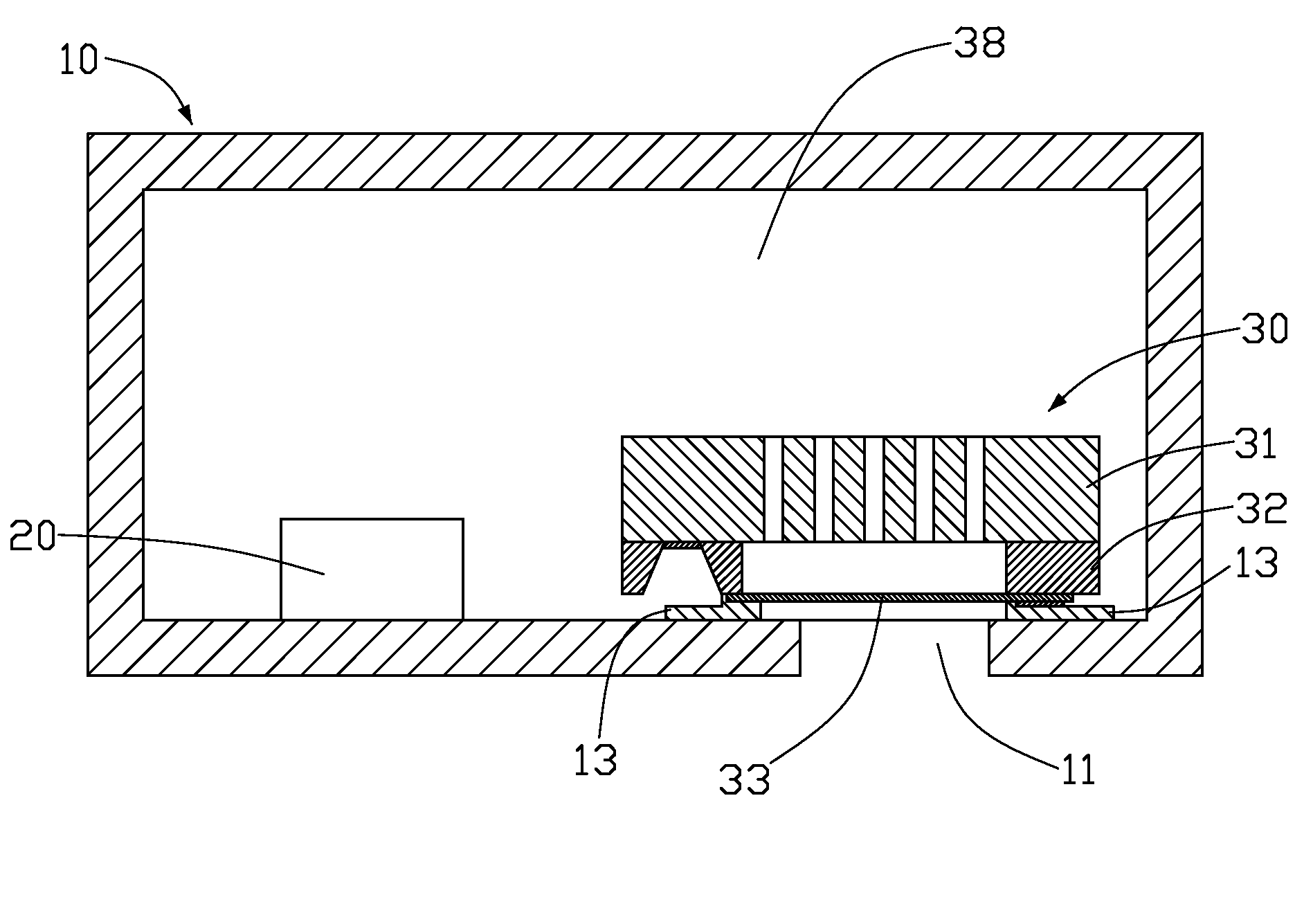
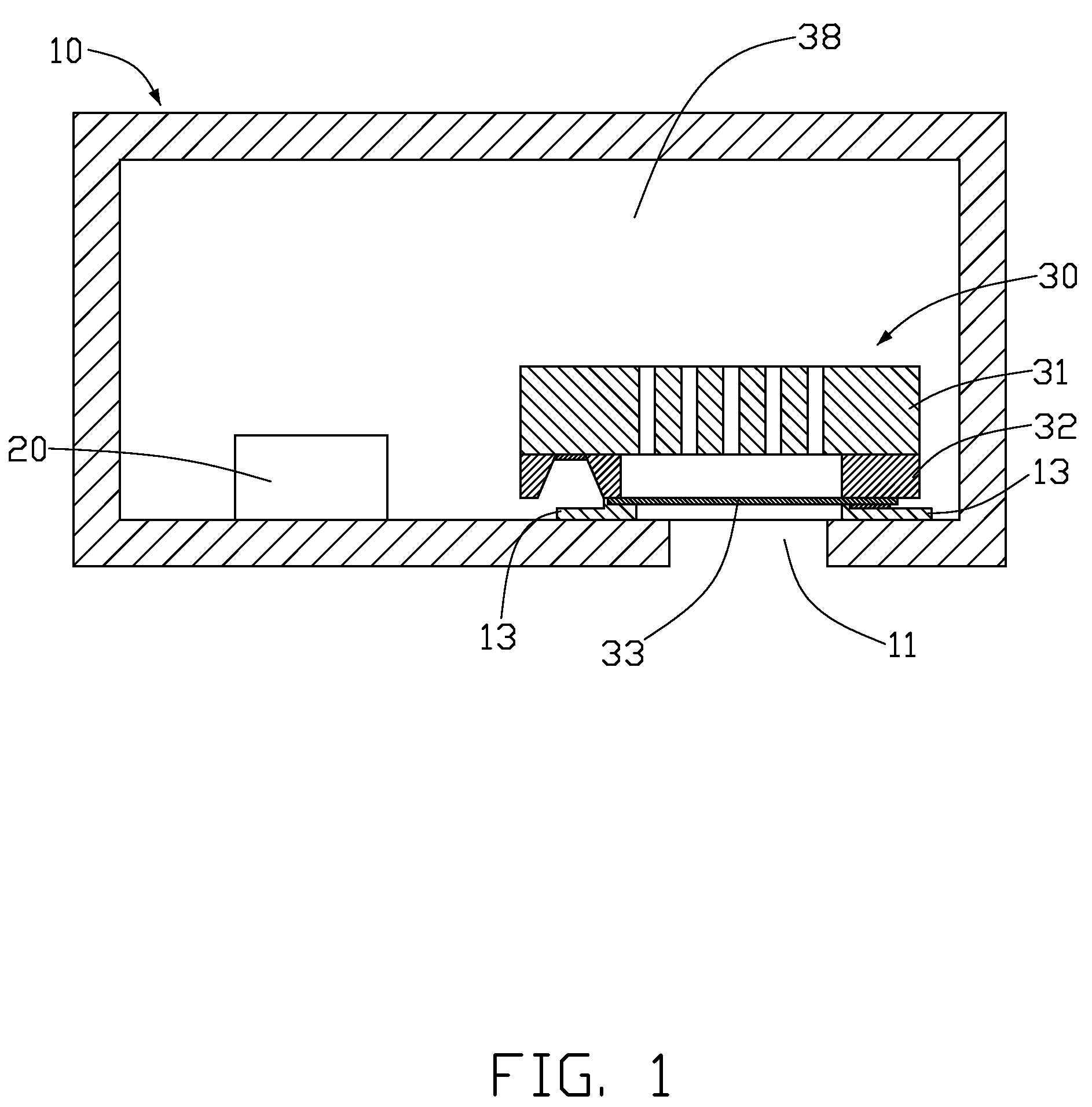
[0025]FIG. 1 is an isometric view of an MEMS (micro electromechanical system) microphone in accordance with a first embodiment of the present invention. The MEMS microphone includes a sealed casing 10, a microphone chip 30 arranged in the casing 10, and circuits 20 disposed in the sealed casing 10 and electrically connected with the microphone chip 30.
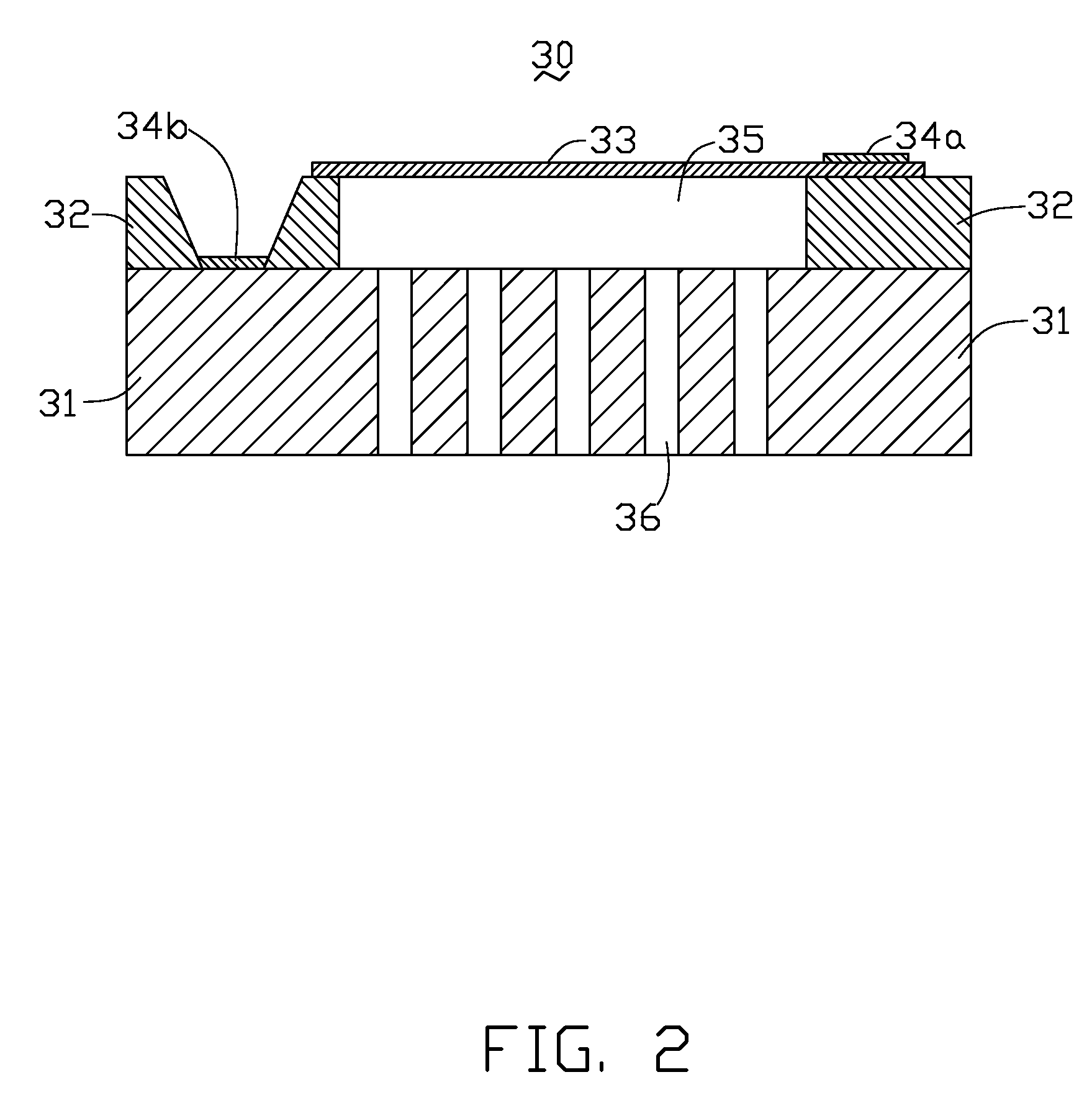
[0026]Referring to FIG. 2, the microphone chip 30 includes a back plate 31, an isolation layer 32, a flexible oscillating diaphragm 33 and first and second electrodes 34a, 34b.
[0027]The back plate 31 is made of doped P-type silicon, doped N-type silicon, or intrinsic silicon. Preferably, the back plate 31 is made of a P+-doped polysilicon. The back plate 31 functions as a fixed electrode plate and a substrate of the microphone chip 30. The isolation layer 32, the diaphragm 33, and the first and second electrodes 34a, 34b are disposed on ...
second embodiment
[0048]Referring to FIG. 20, the isolation layer 32 is etched through the holes 46 so as to form the air interstice 35 via dry etching method such as ICP (inductive coupled plasma) method or RIE (reactive ion etching) method, or wet etching method, or release-etching method. The mask layer 58d is removed from the back plate 41 so as to form the microphone chip 40 of the
[0049]Furthermore, a passivation layer 58 is deposited on the back plate 41 after the mask layer 58d is removed. The microphone chip 50 of the third embodiment is obtained. Alternatively, the mask layer 58d can function as the passivation layer 58 of the third embodiment. In this case, there is no need to get rid of the mask layer 58d from the back plate 41.
[0050]In the present methods, the microphone chip 30 of the first embodiment can be made by the method shown inFIGS. 16 to 20. Under this status, there is no need to form the assistant conductive layer 47 on the silicon substrate 41d of FIG. 16. Similarly, the micro...
PUM
 Abstract
Description
Claims
Application Information
 - R&D
- Intellectual Property
- Life Sciences
- Materials
- Tech Scout
- Unparalleled Data Quality
- Higher Quality Content
- 60% Fewer Hallucinations
Browse by: Latest US Patents, China's latest patents, Technical Efficacy Thesaurus, Application Domain, Technology Topic, Popular Technical Reports.
© 2025 PatSnap. All rights reserved.Legal|Privacy policy|Modern Slavery Act Transparency Statement|Sitemap|About US| Contact US: help@patsnap.com


