Wideband temperature compensated resonator and wideband VCO

a resonator and temperature compensation technology, applied in the field of resonators, can solve the problem that the open loop oscillating frequency of the vco output signal is seen to change with temperature, and achieve the effect of reducing parasitic capacitance, less parasitic capacitance, and facilitating increased tuning rang

Active Publication Date: 2012-08-28
QUALCOMM INC
View PDF25 Cites 29 Cited by
  • Summary
  • Abstract
  • Description
  • Claims
  • Application Information

AI Technical Summary

Benefits of technology

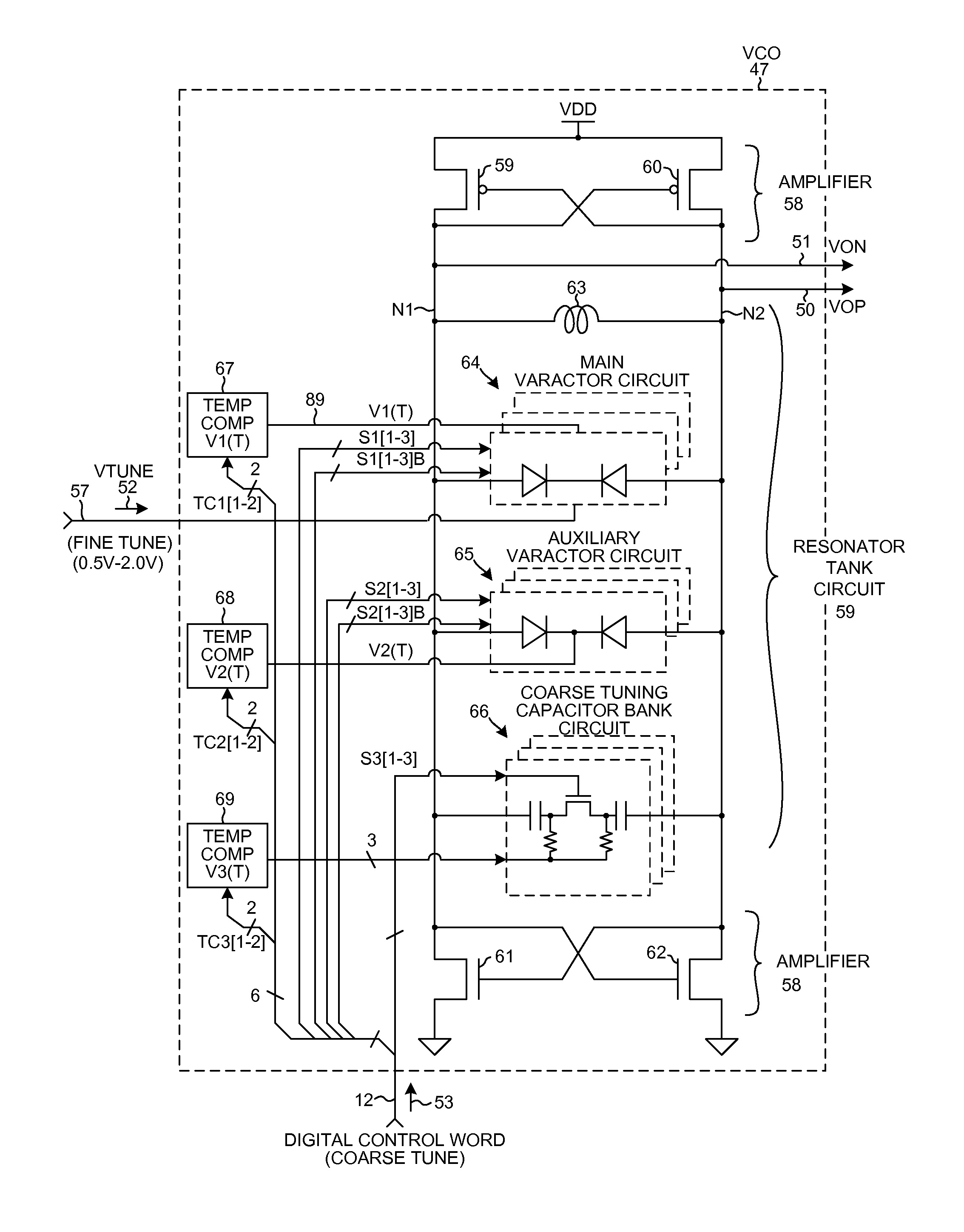
[0012]Accordingly, in one example, all disabled main varactor circuit portions, all disabled auxiliary varactor circuit portions, and all disabled capacitor bank circuit portions are usable for temperature compensation purposes. By appropriate control of which main varactor circuit portions are enabled, which auxiliary varactor circuit portions are enabled, which capacitor bank circuit portions are enabled, and how the temperature compensation analog voltages V1(T), V2(T) and V3(T) vary as a function of temperature, a VCO of which the resonator is a part is made to have an output signal oscillating frequency variation over temperature (−30 degrees Celsius to +110 degrees Celsius) of less than plus or minus 0.02 percent for any VCO output frequency in a wideband frequency range from 2.5 GHz to 5.0 GHz. Because all varactors coupled to the resonator tank nodes that are not used for tuning are usable for temperature compensation, no extra capacitance must be added just for temperature compensation. Accordingly, there is less parasitic capacitance on the resonator tank nodes and this reducing of parasitic capacitance on the resonator tank nodes facilitates increased tuning range.

Problems solved by technology

Unfortunately, the open loop oscillating frequency of the VCO output signal is seen to change with temperature.
This is undesirable.

Method used


Image

  • Wideband temperature compensated resonator and wideband VCO
  • Wideband temperature compensated resonator and wideband VCO
  • Wideband temperature compensated resonator and wideband VCO

Examples


Embodiment Construction

[0037]FIG. 5 is a diagram of a mobile communication device 1 that includes a wideband temperature compensated resonator tank in accordance with a first novel aspect. In this example, mobile communication device 1 is a multi-band cellular telephone handset. Device 1 includes (among other parts not illustrated) an antenna 2 usable for receiving and transmitting cellular telephone communications, an RF (Radio Frequency) transceiver integrated circuit 3, and a digital baseband processor integrated circuit 4. In some examples, the transceiver circuitry and the digital baseband circuitry are implemented on the same integrated circuit, but a two integrated circuit implementation is set forth here for illustration purposes.

[0038]Digital baseband integrated circuit 4 includes a processor 5 that executes a program 6 of processor-executable instructions. Program 6 is stored in a processor-readable medium 7 that in this case is a semiconductor memory. Processor 5 accesses memory 7 via a local b...


PUM


Abstract

A resonator of a VCO includes a fine tuning main varactor circuit, an auxiliary varactor circuit, and a coarse tuning capacitor bank circuit coupled in parallel with an inductance. The main varactor circuit includes a plurality of circuit portions that can be separately disabled. Within each circuit portion is a multiplexing circuit that supplies a selectable one of either a fine tuning control signal (FTAVCS) or a temperature compensation control signal (TCAVCS) onto a varactor control node within the circuit portion. If the circuit portion is enabled then the FTAVCS is supplied onto the control node so that the circuit portion is used for fine tuning. If the circuit portion is disabled then the TCAVCS is supplied onto the control node so that the circuit portion is used to combat VCO frequency drift as a function of temperature. How the voltage of the TCAVCS varies with temperature is digitally programmable.

Description

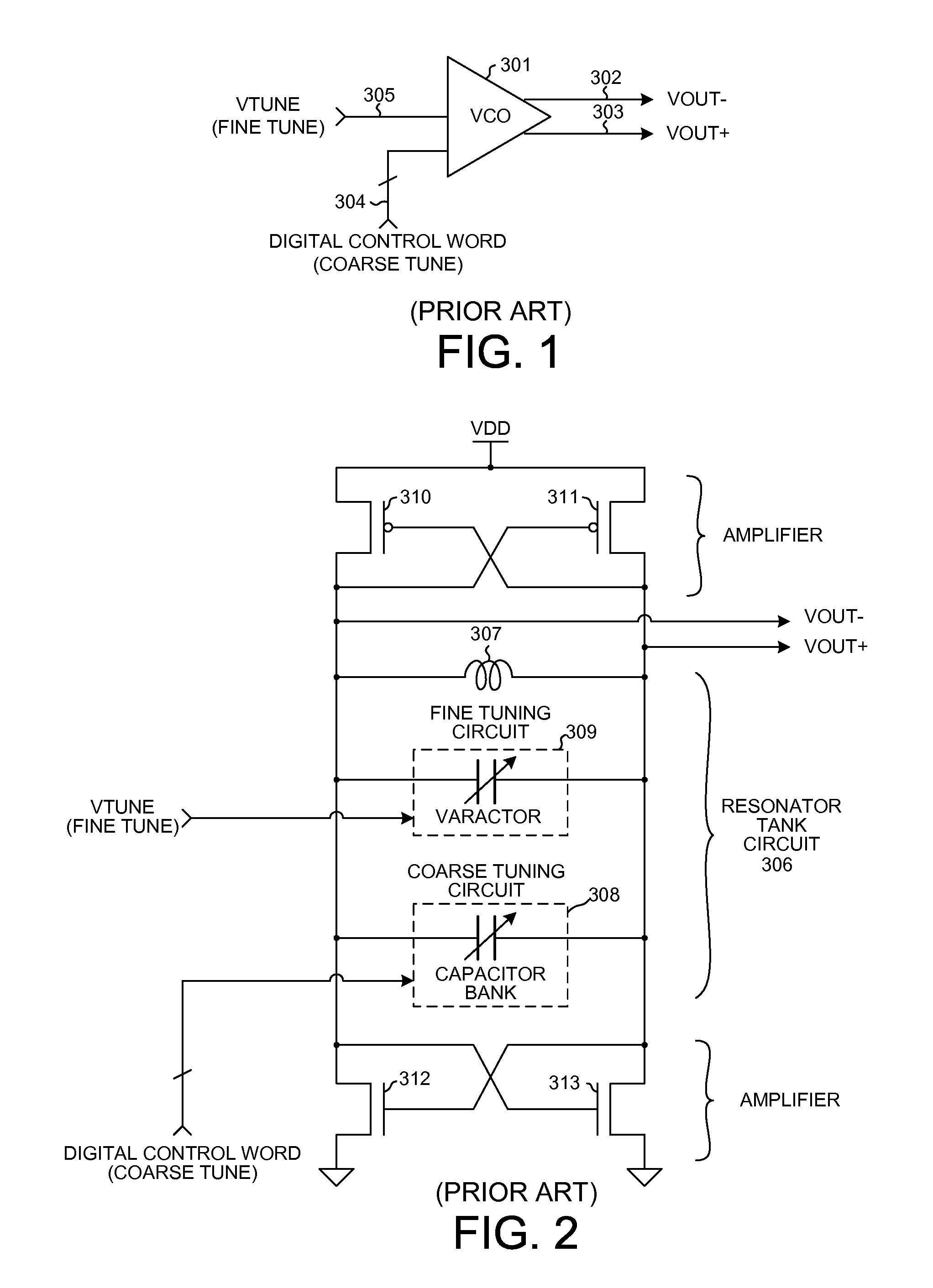
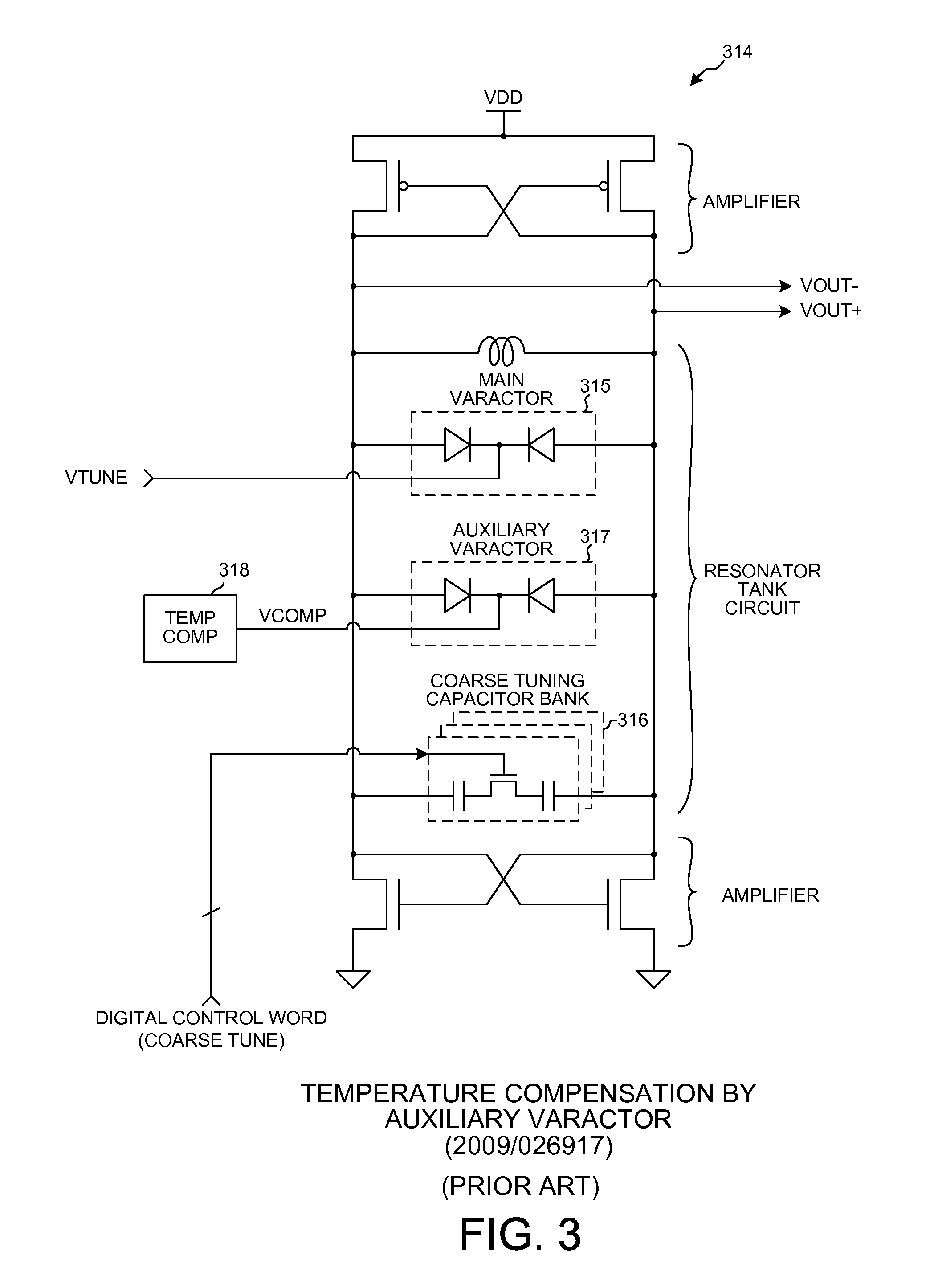
BACKGROUND[0001]1. Technical Field[0002]The present disclosure relates to resonators involving varactors, and more particularly to wideband temperature compensated resonators involving varactors such as resonators usable in wideband Voltage Controlled Oscillators (VCOs).[0003]2. Background Information[0004]Resonators are used in many different types of electronic circuits. One type of resonator involves an inductive element coupled in parallel with a capacitive element. An application of such a resonator is a Voltage Controlled Oscillator (VCO) such as a VCO found in a Phase-Locked Loop (PLL). FIG. 1 (Prior Art) is a diagram of one such type of VCO 31. VCO 301 generates an oscillating VCO output signal. In the illustrated example, the oscillating VCO output signal is a differential sinusoidal signal involving signal VOUT− on conductor 302 and VOUT+ on conductor 303. The frequency of the oscillating VCO output signal is determined by a multi-bit digital coarse tune control word recei...

Claims


Application Information

Patent Timeline
Patent Type & Authority Patents(United States)
IPC IPC(8): H03C3/22H03L1/02
CPCH03B5/04H03L1/023H03L1/025H03L7/099H03L7/104H03L7/1976H03B5/1228H03B5/1212H03B5/1243H03B5/1265H03B5/12H03L1/02
Inventor LIU, LINARATHONG, CHIEWCHARN
Owner QUALCOMM INC
Why Eureka
Try Eureka