Compensation of dose inhomogeneity and image distortion

a dose inhomogeneity and image distortion technology, applied in the field of maskless particlebeam exposure apparatus, can solve the problem of unavoidable influence of the dose rate per beam

Active Publication Date: 2012-09-04
IMS NANOFABTION
View PDF17 Cites 29 Cited by
  • Summary
  • Abstract
  • Description
  • Claims
  • Application Information

AI Technical Summary

Benefits of technology

[0022]In view of the above, it is the task of the present invention to find a way to overcome the deficiencies of prior art and allow an improved control of the dose rate (dose per beam per gray level) and relative placement of the beams in the multi beam array in order to form an array of beams which, at its final position on the target, is undistorted and has an identical dose increment per gray level (i.e. for equal “beam on” interval) and practically identical beam shape. In other words, the task of the invention is to allow a very efficient bitmap coding of the writing data stream, which can be done in “real time” using an online data preparation module, based on identical beams distributed on an ideal grid. According to the basic idea of the invention, the relative placement of the beams is accomplished by pre-distortion of the array of apertures in the BAA (pattern definition device), and the dose rate correction is done by adapting the sizes of apertures according to the current density of the illuminating beam.
[0023]As has been well established in the state of the art, the dose rate per beam is unavoidably influenced by the local current density generated by the illuminating beam, which is generally a radial function of the distance from the optical axis. The distortion of the image caused by distortion errors of the projection system is as well generally a function of the radial distance (i.e., the distance from a center, usually the distance from the optical axis). Therefore, a leveling of the dose rate and relative position correction (pre-distortion) over the radial distance is highly desirable. Both, current density variation and distortion can be pre-calculated quite accurately using state-of-the-art charged particle optics calculation routines which include space charge and very precise field calculation. Moreover, generally, the distortion of the image caused by distortion errors of the projection system may be a function not only of the radial distance; rather, in particular when particle-optical components that do not have radial symmetry (such as multipole electrodes) the distortion may depend on the azimuthal angle as well.
[0027]The present invention allows for an efficient correction of the mentioned beam and imaging defects by means of a suitable adjustment of position and / or size of the apertures in the aperture plate (this means that, preferably, the apertures have the same shape but may have varying size). Thus, the present invention enhances the precise lithographic definition of the image to be produced on the target, and ensures a high resolution of the individual features of the image, independently of the relative position of the beams with respect to the optical axis. Furthermore, the invention allows an efficient bitmap coding of the dose distribution needed to produce the “as designed” structure on the substrate. Bitmap coding is necessary to employ fast algorithms for transforming a designed pattern (for example given as GDSII file) into a data stream that can be handled by the BAA and data path elements. For high throughput applications the BAA has generally a limited number of possible gray levels due to limited space for addressing lines and limited clock speed of the ASIC structure embedded in the aperture membrane.
[0029]The positions of the openings in the blanking plate are chosen in correspondence with those of the apertures, usually with a sufficient size so as to allow clear passage of the beamlet even taking into account position deviation and tolerance of the corresponding aperture. In other words, the corresponding openings in the blanking means are arranged in an arrangement of openings; this arrangement may also be based on a basic arrangement but has deviations from the basic arrangement. The arrangement of the apertures of the aperture array may be chosen different to the arrangement of the corresponding openings of the blanking means, for instance to allow for a relaxed variation in the blanking openings as compared to the apertures. This is possible since it is the apertures which define the shape and position of the beamlets, whereas the blanking openings should allow passage to the beam anyway, while the blanking deflectors may introduce a deflection of the individual beamlet according to the desired pattern.

Problems solved by technology

As has been well established in the state of the art, the dose rate per beam is unavoidably influenced by the local current density generated by the illuminating beam, which is generally a radial function of the distance from the optical axis.

Method used


Image

  • Compensation of dose inhomogeneity and image distortion
  • Compensation of dose inhomogeneity and image distortion
  • Compensation of dose inhomogeneity and image distortion

Examples


Embodiment Construction

[0049]It should be appreciated that the invention is not restricted to the embodiments discussed in the following, which merely represent possible implementations of the invention.

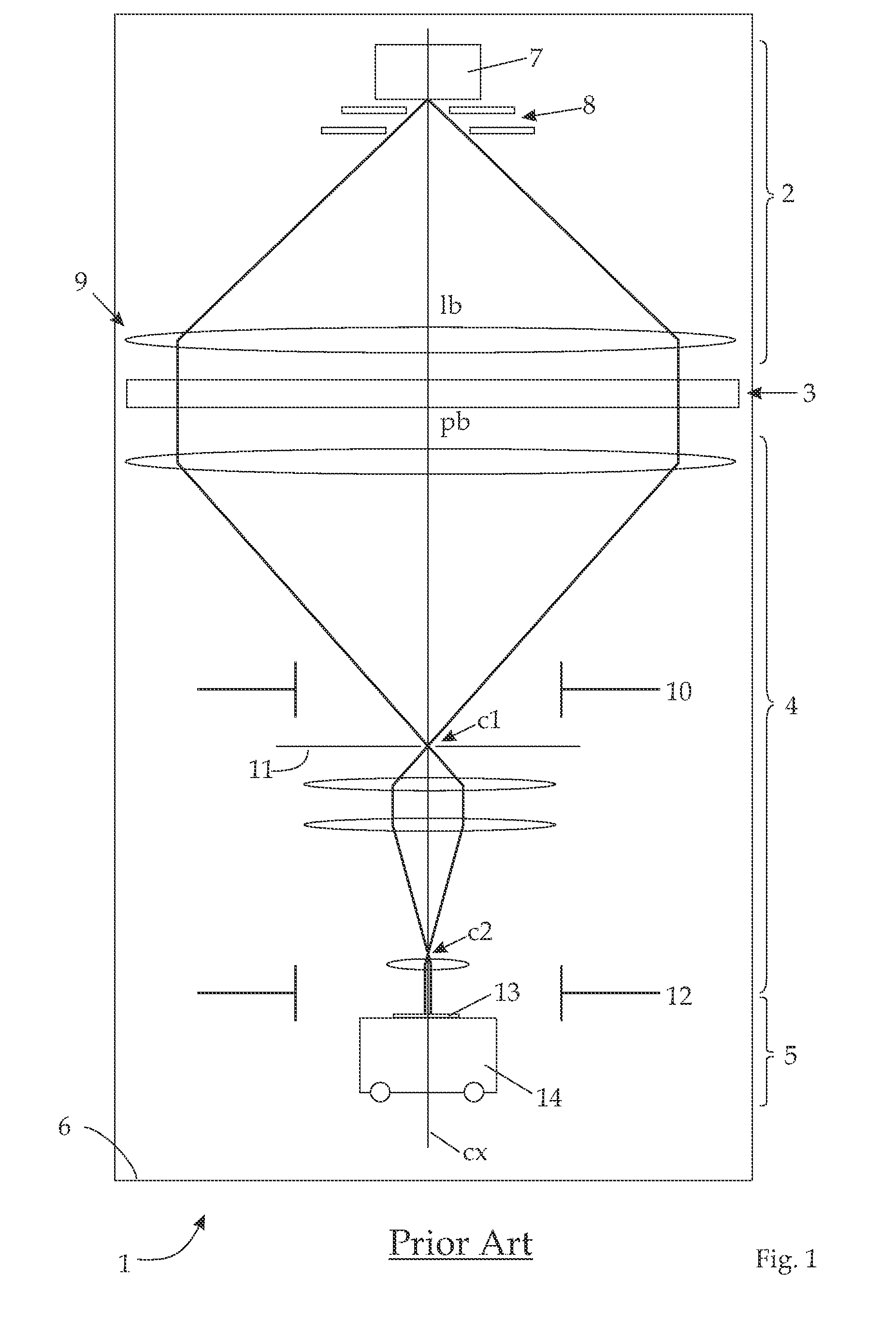
[0050]An overview of a lithographic apparatus employing the preferred embodiment of the invention is shown in FIG. 1. Such a lithographic apparatus is well known in prior art. In the following, only those details are given as needed to disclose the invention; for the sake of clarity, the components are not shown to size in FIG. 1. The main components of the lithography apparatus 1 are—corresponding to the direction of the lithography beam lb, pb which in this example runs vertically downward in FIG. 1—an illumination system 2, a pattern definition (PD) system 3, a projecting system 4, and a target station 5 with the substrate 13. The whole apparatus 1 is contained in a vacuum housing 6 held at high vacuum to ensure an unimpeded propagation of the beam lb, pb along the optical axis cx of the apparatus. The ...


PUM


Abstract

An improved aperture arrangement in a device for defining a pattern on a target, for use in a particle-beam exposure apparatus, by being irradiated with a beam of electrically charged particles and allowing passage of the beam only through a plurality of apertures. The device includes an aperture array having a plurality of apertures of identical shape defining the shape and relative position of beamlets permeating the apertures. A blanking device switches off the passage of selected beamlets permeating the apertures and defined by them. The apertures are arranged on the aperture array according to an arrangement deviating from a regular arrangement by small deviations, adjusting for distortions caused by the particle-beam exposure apparatus, and the size of the apertures of the aperture array differs across the aperture array in order to allow for an adjustment of the current radiated on the target through the apertures and the corresponding openings.

Description

FIELD OF THE INVENTION[0001]The invention relates to a maskless particle-beam exposure apparatus for forming a pattern on a surface of a substrate or target by means of a beam of energetic electrically charged particles. More in detail, the invention relates to a pattern definition means and an exposure apparatus employing this pattern definition means. In particular, the pattern definition means is a device for defining a pattern in a particle-beam exposure apparatus, which device is adapted to be irradiated with a beam of electrically charged particles and let pass the beam only through a plurality of apertures. It comprises an aperture array means which has a plurality of apertures of defined shape defining the shape and relative position of beamlets permeating said apertures, and further a blanking means to switch off the passage of selected beamlets. This blanking means has a plurality of openings, each opening corresponding to a respective aperture of the aperture array means ...

Claims


Application Information

Patent Timeline
Patent Type & Authority Patents(United States)
IPC IPC(8): A61N5/00
CPCB82Y10/00B82Y40/00G03F1/20G03F7/2059G03F7/70433H01J37/3174
Inventor PLATZGUMMER, ELMARFRAGNER, HEINRICHCERNUSCA, STEFAN
Owner IMS NANOFABTION
Why Eureka
Try Eureka