Feed-back and feed-forward systems and methods to reduce oscillator phase-noise

a technology of phase noise reduction and feed-forward, which is applied in the direction of pulse automatic control, modulation, and electrical characteristics varying frequency control, etc., can solve the problems of incompatible with standard silicon processing technology, noisy q>100 resonators at ghz range, and inability to advance wireless and wired communication

Active Publication Date: 2012-09-04
UNIV OF SOUTHERN CALIFORNIA
View PDF7 Cites 16 Cited by
  • Summary
  • Abstract
  • Description
  • Claims
  • Application Information

AI Technical Summary

Problems solved by technology

The advancements of wireless and wired communications would not be possible without accurate frequency synthesizers that are at the core of synchronous and coherent transceivers.
In real-world implementations though, all practical oscillators have been shown to be noisy.
In the context of electrical oscillators, unfortunately, extremely high-Q (Q>100) resonators at GHz range are not compatible with standard silicon processing technologies.
This is due to the loss of typical materials that are used in a standard silicon process and also the small available volume to store energy in an Integrated Circuit (IC).
The downside of such a scheme is that the generated frequency cannot be tuned.
Hence, improvement in phase noise beyond certain limit is not possible.
Typically, the frequency tuning resolution of a PLL-based frequency synthesizer is limited (e.g., a few KHz).
Also, as common with all feedback systems the frequency switching time in PLL-based systems is slow.
The power consumption of DDS solutions are very high (several Watts in the GHz range), which makes them unusable for most consumer products (e.g., portable devices).

Method used


Image

  • Feed-back and feed-forward systems and methods to reduce oscillator phase-noise
  • Feed-back and feed-forward systems and methods to reduce oscillator phase-noise
  • Feed-back and feed-forward systems and methods to reduce oscillator phase-noise

Examples


Embodiment Construction

[0033]Illustrative embodiments are now discussed. Other embodiments may be used in addition or instead. Details that may be apparent or unnecessary may be omitted to save space or for a more effective presentation. Conversely, some embodiments may be practiced without all of the details that are disclosed.

[0034]Aspects of the present disclosure are directed to phase noise cancellation for electrical oscillators. An aspect of the present disclosure includes feed-forward phase noise cancellation / reduction based on relatively fast phase-noise measurement. Another aspect of the present disclosure includes utilization of feedback to the oscillator itself for phase-noise cancellation / reduction.

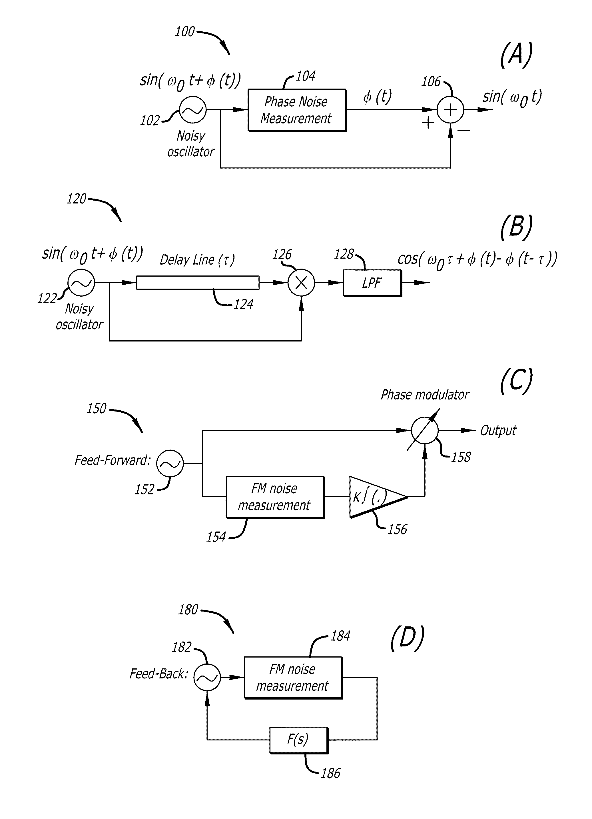
[0035]FIG. 1A depicts a simplified schematic of a circuit illustrating the basic principle behind a feed-forward phase noise cancellation scheme, according to exemplary embodiments of the present disclosure. The circuit 100 includes oscillator 102, a phase noise measurement block 104, and a summer (...


PUM


Abstract

Systems, methods, and apparatus are described that provide for low phase-noise, spectrally-pure, and low-jitter signals from electrical oscillators. An aspect of the present disclosure includes utilization of an open-loop feed-forward phase-noise cancellation scheme to cancel phase noise, or jitter, of an electrical oscillator. Phase noise can be measured and then subtracted, with the phase noise measurement and subtraction being performed at a speed faster than phase noise variations of the oscillator. Another aspect of the present disclosure includes use of a feedback scheme for phase noise reduction. A feedback scheme can be used alone or in conjunction with a feed-forward scheme. Related phase-noise cancellation and / or reduction methods are described. Notch filter and RF amplifier circuits are also described.

Description

CROSS-REFERENCE TO RELATED APPLICATIONS[0001]This application is based upon and claims priority to the following: U.S. Provisional Patent Application No. 61 / 161,354 entitled “METHOD TO REALIZE LOW-PHASE-NOISE, SPECTRALLY PURE, AND LOW-JITTER ELECTRICAL OSCILLATORS AND LASERS,” filed Mar. 18, 2009, the entire content of which is incorporated herein by reference.BACKGROUND[0002]1. Technical Field[0003]This disclosure relates to noise reduction in electrical oscillators.[0004]2. Description of Related Art[0005]Over the past few decades, integrated electronic systems have witnessed an exponential increase in performance and reduction in cost. The majority of electronic systems rely on an accurate frequency source (sometime referred to as a reference clock). The advancements of wireless and wired communications would not be possible without accurate frequency synthesizers that are at the core of synchronous and coherent transceivers. The performance of these systems is directly related t...

Claims


Application Information

Patent Timeline
Patent Type & Authority Patents(United States)
IPC IPC(8): H03L7/00H03B28/00H03C3/02
CPCH03F3/45188H03H7/0115H03L7/099H03L7/18H03B5/364H03F2203/45386H03F2203/45638H03H7/18H03H2007/013H03L1/00H03H7/1758H03H7/1725H03B2200/0066
Inventor GOEL, ANKUSHIMANI, ALIREZAHASHEMI, HOSSEIN
Owner UNIV OF SOUTHERN CALIFORNIA
Why Eureka
Try Eureka