Actuating device for an on/off valve

Active Publication Date: 2012-09-11
SIEMENS AG
View PDF13 Cites 14 Cited by
  • Summary
  • Abstract
  • Description
  • Claims
  • Application Information

AI Technical Summary

Benefits of technology

[0008]It is therefore an object of the invention to provide a way to perform partial strok

Problems solved by technology

The predefined position at which the position switch opens is selected such that ongoing operation of the installatio

Method used


Image

  • Actuating device for an on/off valve
  • Actuating device for an on/off valve

Examples


Embodiment Construction

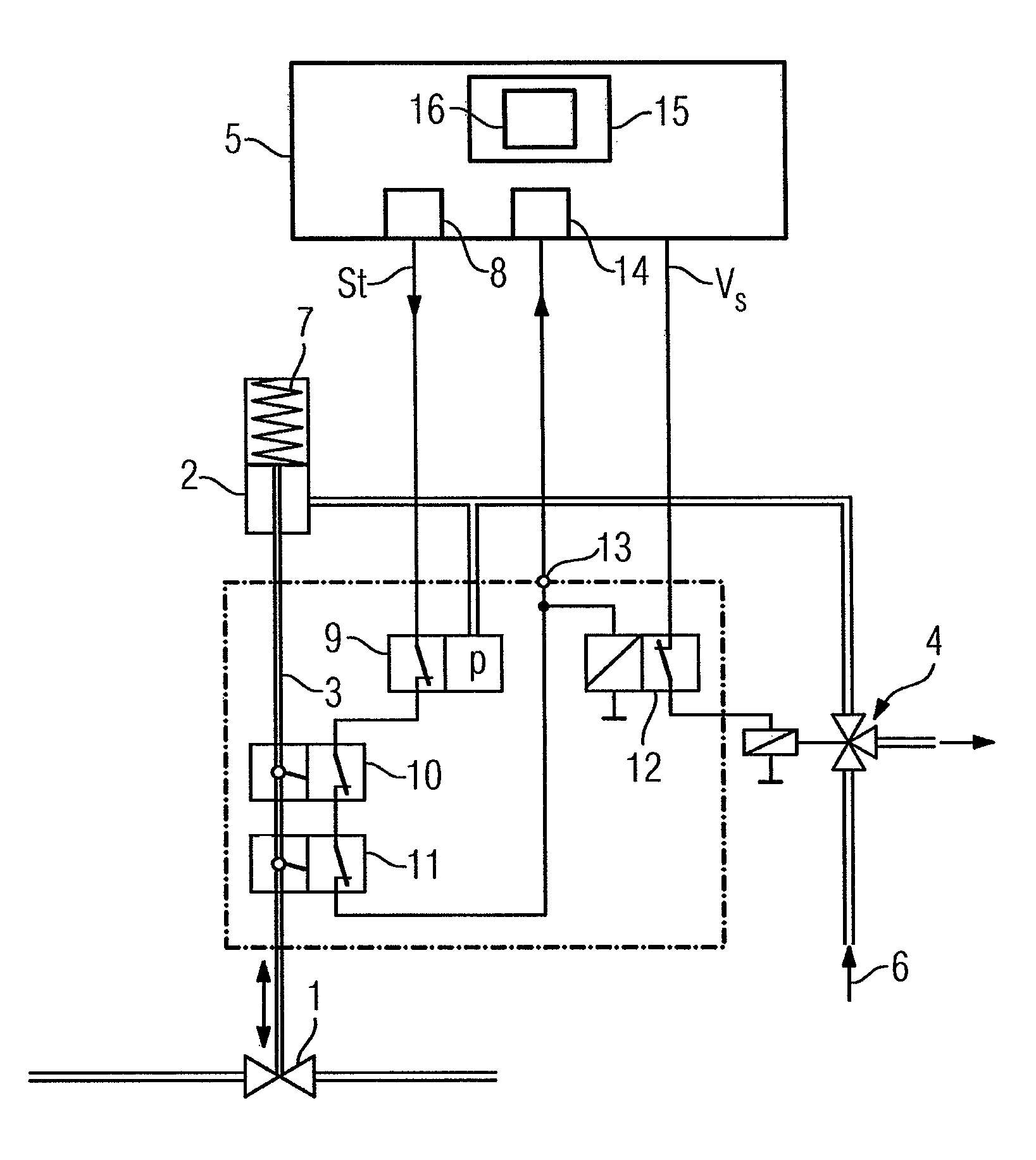
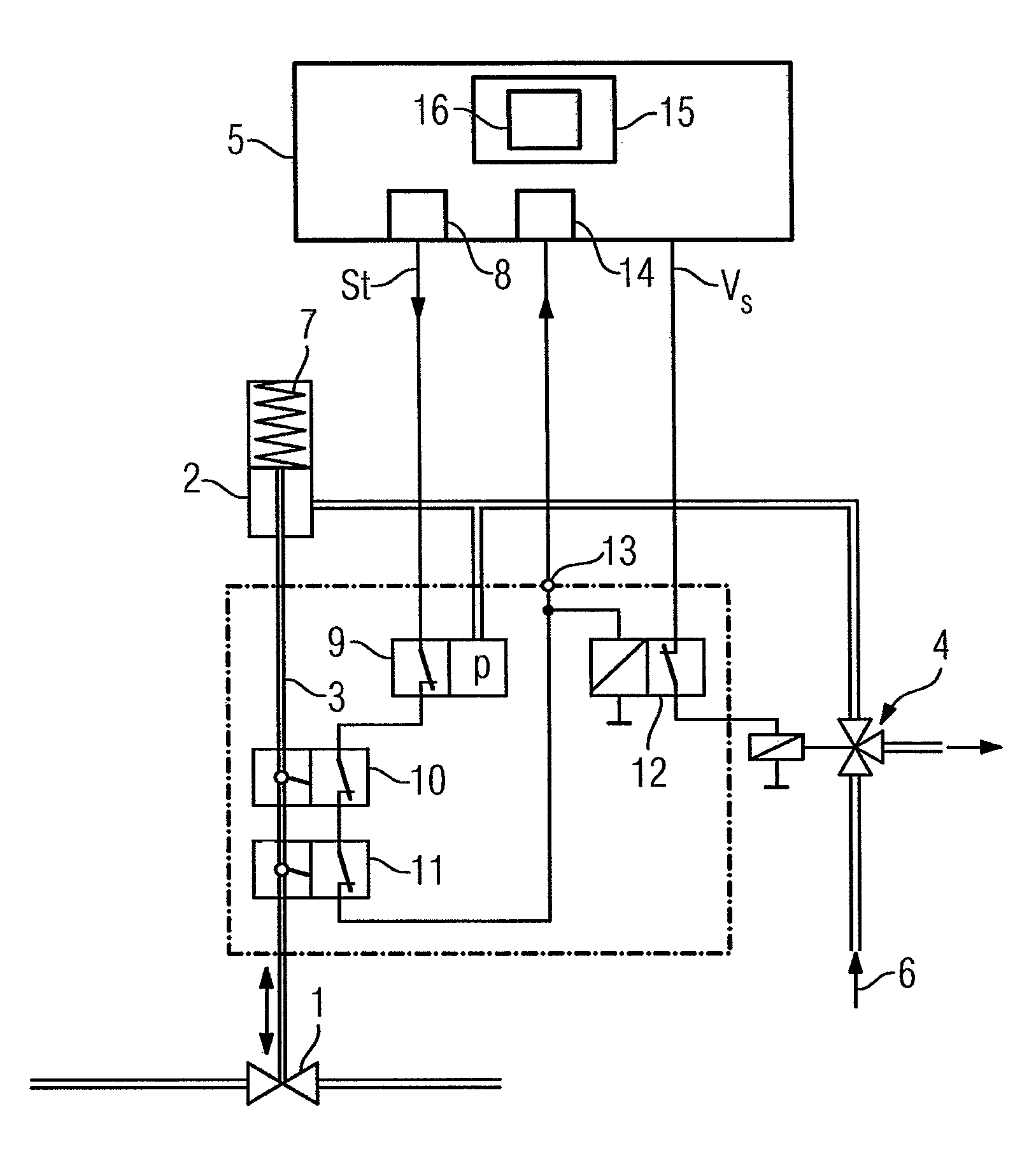
[0018]The actuating device illustrated in the figure has an on / off valve 1 which can be moved either into an operating position, for example “on”, or into a safety position, for example “off”, using a pneumatic drive 2 via an actuating element 3, here in the form of a lifting rod. A solenoid valve 4 which is driven with a control voltage VS provided by a control system 5 connects the pneumatic drive 2 to a compressed air supply 6. In an emergency, the control voltage VS is switched off to vent the pneumatic drive 2 through the solenoid valve 4. The pneumatic drive 2 then becomes unpressurized and moves the actuating element 3 with the valve 1, for example, under the action of a spring 7, from the operating position into the safety position.

[0019]In order to be able to check the functionality of the actuating device as part of a partial stroke test, the control system 5 generates a control signal St at predefined times at a binary output 8, which control signal is routed to a control...


PUM


Abstract

An actuating device for an on/off valve having a pneumatic drive that is connected to a compressed air supply by a solenoid valve, wherein when driven with a control voltage, the solenoid valve ventilates the pneumatic drive with the compressed air and, when the control voltage is not present, vents the pneumatic drive. The pneumatic drive moves the on/off valve into an operating position during ventilation and moves it into a safety position during venting. To permit the performance of partial-stroke tests in the simplest way possible, a device for performing the partial-stroke test includes a controllable switch which is closed in a quiescent state, and in this case supplies the control voltage to the solenoid valve. The controllable switch is opened by a control signal that is generated to perform the partial-stroke test. The control signal is supplied to the controllable switch by a position switch that is closed in the operating position of the on/off valve and is opened when the on/off valve reaches a predefined position in the direction of the safety position.

Description

CROSS-REFERENCE TO RELATED APPLICATIONS[0001]This is a U.S. national stage of International Application No. PCT / EP2008 / 059255, filed on 15 Jul. 2008. Priority is claimed on German Application No. 10 2007 034 059.3, filed on 20 Jul. 2007.BACKGROUND OF THE INVENTION[0002]1. Field of the Invention[0003]The invention relates to an actuating device for an on / off valve having a pneumatic drive which is connected to a compressed air supply by a solenoid valve, wherein the solenoid valve ventilates the pneumatic drive with the compressed air when driven with a control voltage and vents the pneumatic drive when the control voltage is not present, and the pneumatic drive moves the valve into an operating position during ventilation and moves the valve into a safety position during venting, and a means for performing a partial stroke test.[0004]2. Description of the Related Art[0005]In a known actuating device disclosed in DE 10 2006 003 750 A1 or DE 10 2005 004 477 A1, a pneumatic on / off valv...

Claims


Application Information

Patent Timeline
IPC IPC(8): F16K31/02
CPCF16K37/0083G05B23/0256Y10T137/8242
Inventor HEER, KLAUS-PETERHIRSCH, VOLKER
Owner SIEMENS AG
Why Eureka
Try Eureka