Planar optical waveguide element, chromatic dispersion compensator, methods for designing chromatic dispersion compensator, optical filter, methods for designing optical filter, optical resonator and methods for designing optical resonator

a technology of chromatic dispersion compensator and waveguide element, which is applied in the direction of optical elements, multiplex communication, instruments, etc., to achieve the effect of reducing the polarization dependence of optical characteristics, achieving even more easily bragg grating pattern on the core top portion, and shortening the waveguide length

Active Publication Date: 2012-09-18
FUJIKURA LTD
View PDF46 Cites 7 Cited by
  • Summary
  • Abstract
  • Description
  • Claims
  • Application Information

AI Technical Summary

Benefits of technology

[0053]According to the exemplary aspect described in (1) above, a planar optical waveguide element having a Bragg grating pattern can reduce the polarization dependence of the optical characteristics.
[0054]According to the exemplary aspect described in (2) above, it is possible to construct a structure that enables an arbitrary effective refractive index to be achieved, and it is also possible to form a Bragg grating pattern with a desired accuracy.
[0055]According to the exemplary aspect described in (3) above, it is possible to achieve a Bragg grating pattern on a core top portion even more easily.
[0056]According to the exemplary aspect described in (4) and (5) above, because effective refractive indices can be exactly matched together at each position in the propagation direction of guided light, a planar optical waveguide element having two types of Bragg grating pattern can be achieved more precisely.
[0057]According to the exemplary aspect described in (6) above, it is possible to make the waveguide length shorter than in a sampled grating.
[0058]According to the exemplary aspect described in (7) above, compared to a conventional chirped Bragg grating in which the pitch changes gradually, tolerance control in the manufacturing process is easier and this contributes to an improvement in the manufacturing yield.

Problems solved by technology

However, in the fiber Bragg grating, because there are limits to the range over which the refractive index can be changed in order to manufacture a grating pattern, an operation in which the aforementioned spectrum characteristics are apodized by applying an inverse Fourier transform is also carried out so that these limits are not exceeded.

Method used


Image

  • Planar optical waveguide element, chromatic dispersion compensator, methods for designing chromatic dispersion compensator, optical filter, methods for designing optical filter, optical resonator and methods for designing optical resonator
  • Planar optical waveguide element, chromatic dispersion compensator, methods for designing chromatic dispersion compensator, optical filter, methods for designing optical filter, optical resonator and methods for designing optical resonator
  • Planar optical waveguide element, chromatic dispersion compensator, methods for designing chromatic dispersion compensator, optical filter, methods for designing optical filter, optical resonator and methods for designing optical resonator

Examples


first embodiment

[First Embodiment of a Planar Optical Waveguide Element]

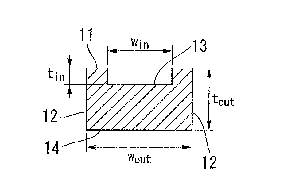
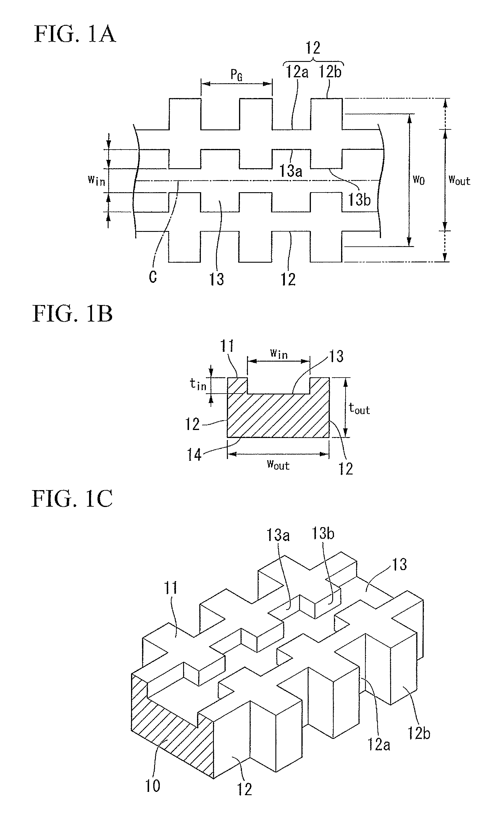
[0161]A first embodiment of the planar optical waveguide element of the present invention is shown in FIG. 1A through FIG. 1C. If the width or thickness of the waveguide in the light propagation direction is changed periodically in an optical waveguide, then the effective refractive index of the optical waveguide also changes periodically, and a Bragg grating can be constructed. In FIG. 1A through FIG. 1C, only the core 10 is shown and the claddings are not shown. However, it is to be assumed that cladding actually surrounds the periphery of the core 10. In addition, a substrate (not shown) is located below the cladding, and a bottom surface 14 of the core 10 is parallel with the substrate surface. The term “horizontal direction” refers to a direction which is parallel to this substrate surface, while the term “vertical direction” refers to a direction which is perpendicular to the substrate surface.

[0162]FIG. 1A is a plan view...

second embodiment

[Second Embodiment of a Planar Optical Waveguide Element]

[0186]An optical wave guide having a cross-sectional structure such as that shown in FIG. 6 can be given as an example of a Bragg grating optical waveguide structure in which polarization dependence has been reduced. On account of the simplified description of the principle of reducing polarization dependence, the cross-sectional structures of the cores 10 are all the same in the planar optical waveguide elements of FIGS. 1A through 1C and FIGS. 3A through 3C. However, if the effective refractive index is changed by changing the dimensions of the optical waveguide, then an optical waveguide having a composite core structure such as that shown in FIG. 6 is preferable in order to improve the accuracy of the effective refractive index.

[0187]The core of the planar optical waveguide element 20 having the cross-sectional structure shown in FIG. 6 is a composite core comprises two areas, namely, inner side cores 21 and 22 and an oute...

example 4

[Example 4 of an Optical Filter]

[0336]The present example is an example of the design of an interleaver for a wavelength channel having intervals of 0.1 THz. In the present example, an optical filter is designed with the channel interval set to 0.2 THz, and with the width of the reflection band of each channel set to 0.1 THz. The specified optical characteristics are shown in FIG. 42. The effective refractive index distribution derived based on an inverse scattering problem solution using these optical characteristics is shown in FIG. 43 and FIG. 44. The results obtained when the effective refractive index was converted to a square-like shaped profile are shown in FIG. 45.

[0337]The optical filter (i.e., the interleaver) of the present example is able to split the signal light of each channel having an interval of 0.1 THz into two paths made up of odd-numbered and even-numbered channels.


PUM


Abstract

There is provided a planar optical waveguide element comprises a core of an optical waveguide; and first Bragg grating pattern and second Bragg grating pattern that are provided on the core, wherein the first Bragg grating pattern and the second Bragg grating pattern are mutually parallel along a propagation direction of guided light.

Description

CROSS-REFERENCE TO RELATED APPLICATION[0001]This is a Continuation Application of International Application No. PCT / JP2009 / 053759, filed on Feb. 27, 2009, which claims priority to Japanese Patent Application No. 2008-049840, filed Feb. 29, 2008. The contents of the aforementioned applications are incorporated herein by reference.TECHNICAL FIELD[0002]Description herein related to a planar optical waveguide element which has two types of Bragg grating pattern, and which can be used in various applications such as chromatic dispersion compensators, optical filters, optical resonators, and the like, and also related to a design methods thereof.BACKGROUND ART[0003]The following are examples of chromatic dispersion compensation in an optical waveguide structure for which polarization dependence is not considered.[0004]A dispersion compensator having a Bragg grating pattern on a waveguide is disclosed in Patent document 1. The dispersion compensator of Patent document 1 has a plurality of ...

Claims


Application Information

Patent Timeline
Patent Type & Authority Patents(United States)
IPC IPC(8): G02B6/34H01S3/00H04J14/02
CPCG02B6/124G02B6/29325G02B6/29394
Inventor OGAWA, KENSUKEGUAN, NINGSAKUMA, KEN
Owner FUJIKURA LTD
Why Eureka
Try Eureka